Quick gray scale transform method for liquid crystal display

A liquid crystal display, fast technology, applied in static indicators, instruments, nonlinear optics, etc., can solve problems such as afterimage, image transition afterimage, image blur, etc.

Inactive Publication Date: 2008-02-27
VASTVIEW TECH
View PDF3 Cites 0 Cited by
  • Summary
  • Abstract
  • Description
  • Claims
  • Application Information

AI Technical Summary

Problems solved by technology

Take Figure 2 to illustrate, each frame (Frame) F on the time axis 1 , F 2 , F 3 , F 4 Each has a different brightness to be displayed. Since it takes time to drive the liquid crystal molecules to twist to produce a brightness change, the brightness change and time correspond to a curve change, as indicated by (a) in the figure. When the desired brightness is reached, the The voltage value is maintained at this bright

Method used


Image

  • Quick gray scale transform method for liquid crystal display
  • Quick gray scale transform method for liquid crystal display
  • Quick gray scale transform method for liquid crystal display

Examples


no. 1 example

[0044] In order to clearly express the technical features of the present invention, an embodiment in which the gate lines of the liquid crystal display are divided into two areas and two scanning signals are synchronously transmitted is firstly described.

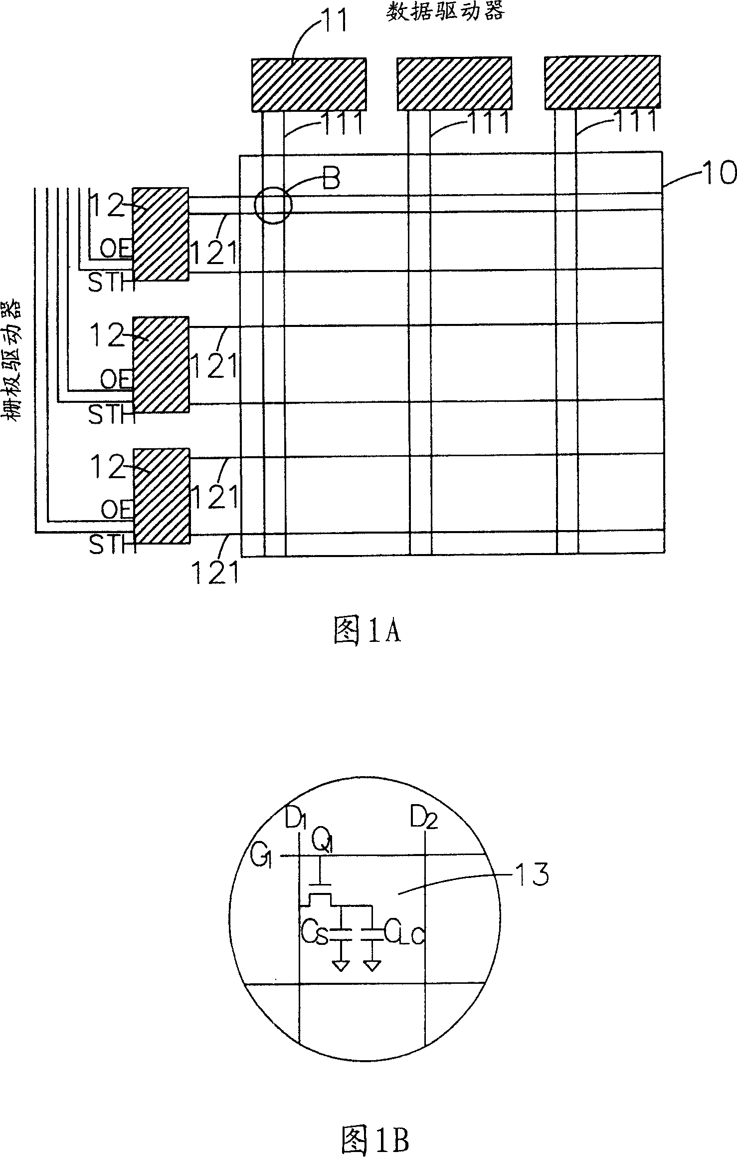
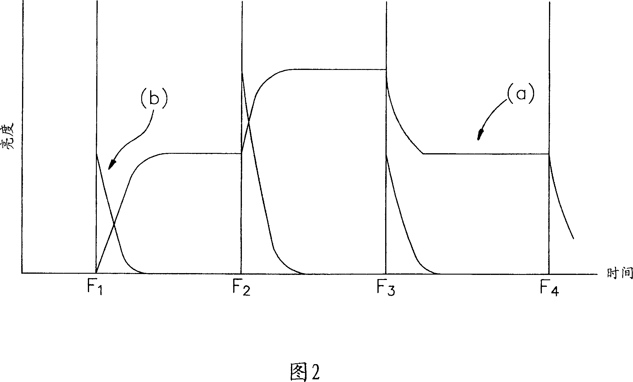
[0045] Please refer to Fig. 5, Fig. 6A and Fig. 6B, Fig. 5 shows the output driving voltage waveform and brightness change curve (a) (b) of a pixel at a gate line position on a display panel, and its horizontal axis represents time, unit is ms, the frame interval time is T, and it is divided into two sub-intervals t 1 , t 2 , and t 1 :t 2 =1:1, FIG. 6A shows that the set gate line on the display panel 40 is divided into two regions M 1 ,M 2 , assuming that the number of gate lines in the first area is m, the number of gate lines in the second area is also m, and the total number of gate lines is 2m, so the ratio of the number of gate lines in the two areas is 1:1.

Embodiment approach

[0046] Assuming that a continuous image data enters the frame interval (Frame N) from the previous frame interval (Frame N-1) and the brightness of the data is code 120, the brightness can select a data voltage from the look-up table (LUT) to drive the display panel 40, To make the display panel 40 reach brightness within a specific time, the implementation method of the fast grayscale conversion of the present invention is as follows:

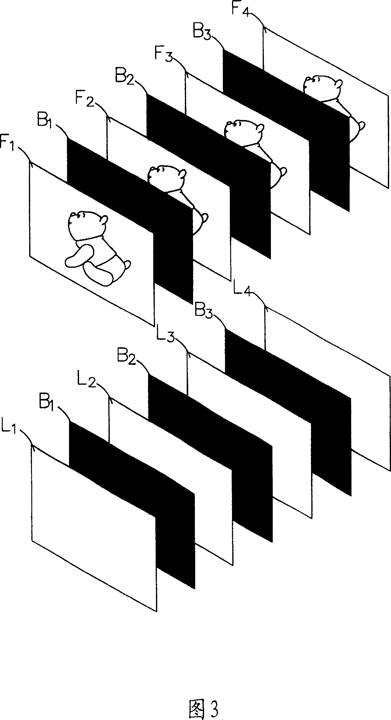
[0047] in the first subinterval t 1 Inside, the gate driver 41 synchronously turns on the two gate lines on the display panel 40, and in the first area M 1 The first gate line G 1 Give the data voltage code120 of the frame interval N, in the second area M 2 The first gate line G m+1 Give the previous frame interval N-1 a voltage code 0 to display a black screen, and then sequentially and synchronously turn on the next gate line of each area, and give the same voltage value as the previous gate line, that is, the gate of the same area The l...

no. 2 example

[0054] The second embodiment is further described by dividing the gate line into three areas and synchronously controlling three scanning signals. Please refer to FIG. 7 , FIG. 8A and FIG. 8B . The output driving voltage waveform and brightness change curve (a)(b) of a pixel at a position, the horizontal axis represents time, the unit is ms, and the frame interval time is T, which is divided into two sub-intervals t 1 , t 2 , t 3 , t 1 :t 2 :t 3 =1:1:1, as shown in FIG. 8A, set the gate lines on the display panel 50 to be divided into three regions M 1 ,M 2 ,M 3 , assuming that the number of gate lines in the first zone is m, the number of gate lines in the second zone is m, the number of gate lines in the third zone is also m, and the total number of gate lines is 3m, the gate lines in the two zones The number ratio is 1:1:1.

[0055] As shown in Figure 7, assuming that a continuous image data enters the frame interval (Frame N) from the previous frame interval (Frame...


PUM


Abstract

A LCD quick gray scale conversion method comprises steps: divide the LCD drive grid line zone to complex zones and frame interval time to complex subintervals accordingly; within time of a synchronous control signal, start first grid lines of every zone by turns, then the hypo grid line, and repeat; wherein, at least one group grid lines supply data voltage for video data and voltage for displaying black picture; repeat, until end interval time of entire frame and come into next frame interval. By division to time and space, it comes to purpose of gray scale conversion quickly, and fit to image process of all kinds of LCD and OLED display.

Description

technical field [0001] The present invention relates to a method for fast grayscale conversion of a liquid crystal display, especially a method, which divides the space of the display and the frame interval of data, and simultaneously controls the gate line voltage of each sub-interval by means of a synchronous control signal. First give the voltage that can achieve the desired brightness, and after reaching the desired brightness, then give the voltage that shows the black screen for fast grayscale conversion, so as to improve the afterimage or image overlap of the LCD display. It is suitable for Image processing for various liquid crystal displays and organic light emitting diode (OLED) displays. Background technique [0002] The popularity of liquid crystal displays is mainly due to their advantages such as low power consumption, light weight, no radiation, and no flicker compared with traditional cathode ray tube (CRT) displays. Become the mainstream of the display indu...

Claims


Application Information

Patent Timeline
IPC IPC(8): G02F1/136G09G3/36
Inventor 沈毓仁陈政嵘
Owner VASTVIEW TECH
Why Eureka
Try Eureka