Air-conditioner
A technology of air conditioners and heat exchangers, applied in space heating and ventilation, heating methods, lighting and heating equipment, etc., can solve problems such as uneven distribution of wind speed, increased noise, and slow wind speed
- Summary
- Abstract
- Description
- Claims
- Application Information
AI Technical Summary
Problems solved by technology
Method used
Image
Examples
Embodiment 1
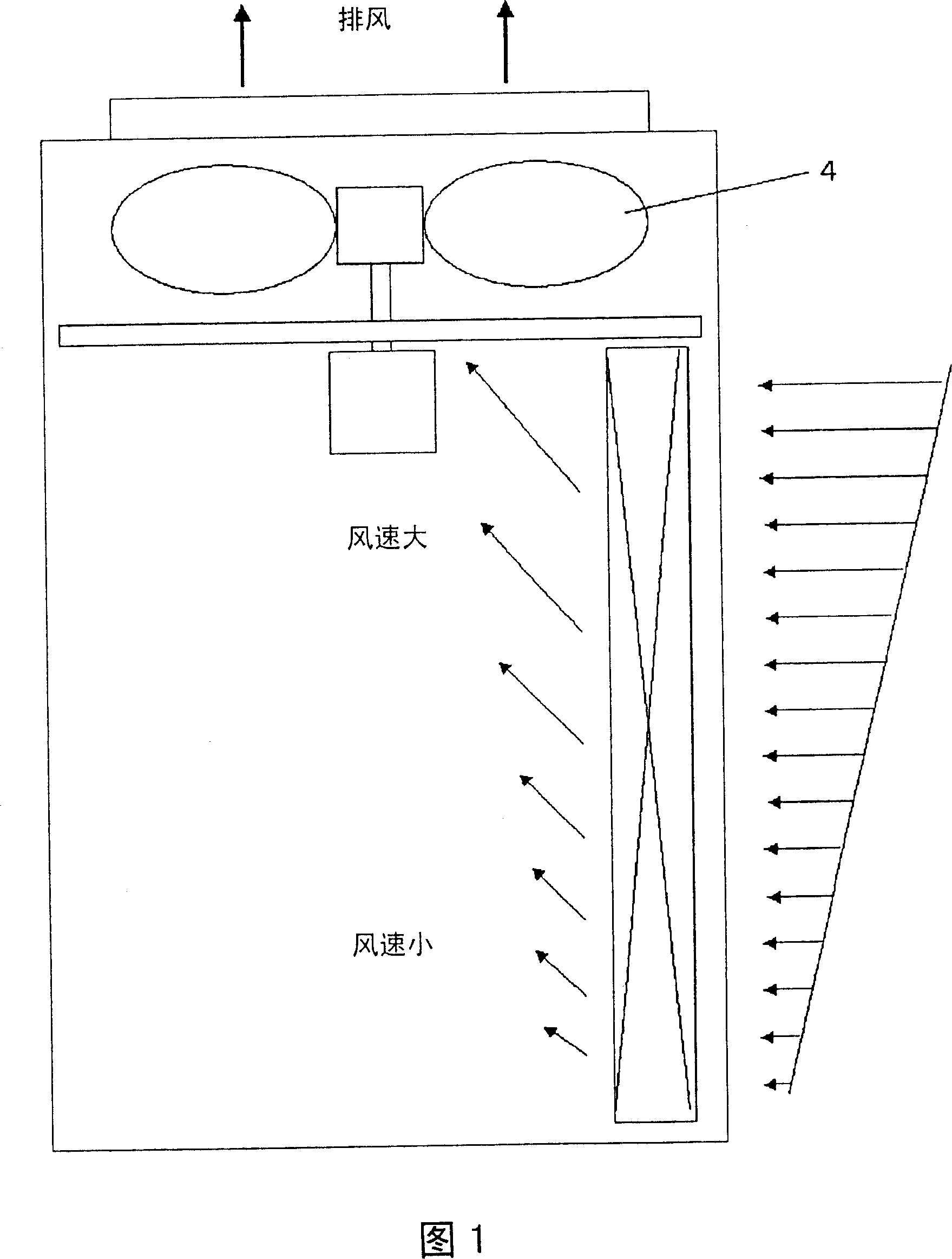
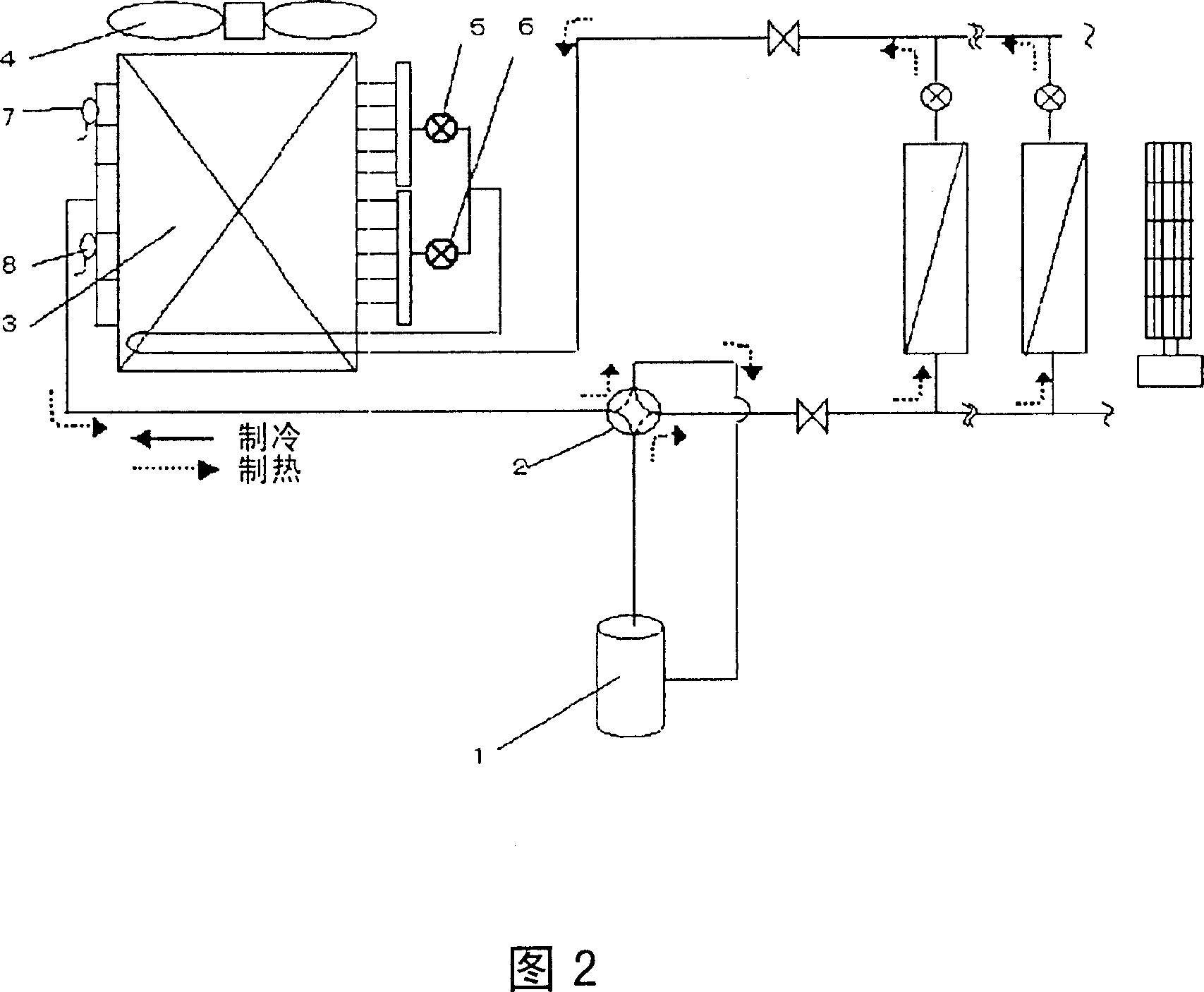
[0037] Fig. 1 is a schematic structural diagram of an outdoor unit in an embodiment of the present invention, in which a multi-flow air conditioner for a building is used as an example for illustration. Fig. 2 is a schematic diagram of the refrigeration cycle system in the present invention.
[0038] The refrigeration cycle system in FIG. 2 includes: a compressor 1 with adjustable power, a four-way valve 2 for switching between heating operation and cooling operation, an outdoor heat exchanger 3 , and an outdoor fan 4 . Wherein, the outdoor heat exchanger 3 is further divided into upper and lower parts, and is respectively provided with an outdoor upper expansion valve 5, an outdoor lower expansion valve 6, an outlet temperature sensor 7 at the upper part of the outdoor heat exchanger, and a lower part of the outdoor heat exchanger. Outlet temperature sensor 8.
[0039] Expansion valves 5 and 6 are driven by stepping motors operated under the control of pulse signals, and the...
Embodiment 2
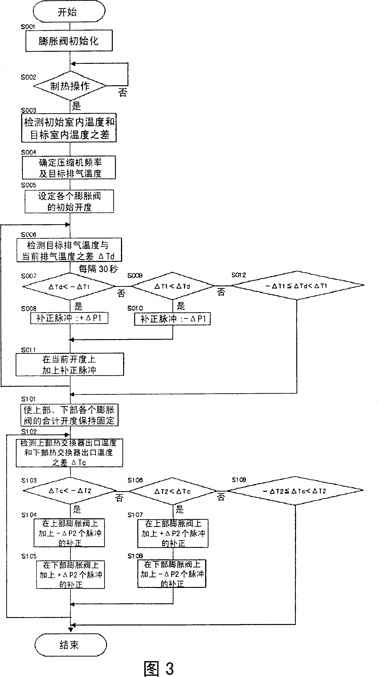
[0046] Fig. 5 and Fig. 6 are the control flowchart of the air conditioner in the second embodiment of the present invention and the timing chart of the control process.
[0047] After the power is turned on, in step S001 the upper and lower expansion valves are initialized to be fully open. Next, if the heating operation is entered in step S002, then according to the difference between the initial indoor temperature and the target indoor temperature in step S003, the compressor frequency and the target discharge temperature are determined in step S004; After each expansion valve is opened up or down for the same number of pulses, it enters the target exhaust temperature control process. The specific control process is: in step S006, the difference ΔTd between the target exhaust temperature and the current exhaust temperature is detected; in step S007, when it is determined that the current exhaust temperature is lower than the target specified value ΔT1, then proceed to step S...
Embodiment 3
[0050] Fig. 7 and Fig. 8 are the control flowchart of the air conditioner in the third embodiment of the present invention and the timing chart of the control process.
[0051] After the power is turned on, firstly, in step S001, the upper and lower expansion valves are initialized to be fully open. Next, if the heating operation is entered in step S002, the compressor frequency and the target discharge temperature are determined in step S004 according to the difference between the initial indoor temperature and the target indoor temperature in step S003; then, in step S005 After the upper and lower expansion valves are opened up or down for the same number of pulses, the target exhaust temperature control process is entered. The specific operation process of this control process is as follows. In step S006, the difference ΔTd between the target exhaust temperature and the current exhaust temperature is detected; if it is determined in step S007 that the current exhaust tempe...
PUM
 Abstract
Description
Claims
Application Information
 - R&D
- Intellectual Property
- Life Sciences
- Materials
- Tech Scout
- Unparalleled Data Quality
- Higher Quality Content
- 60% Fewer Hallucinations
Browse by: Latest US Patents, China's latest patents, Technical Efficacy Thesaurus, Application Domain, Technology Topic, Popular Technical Reports.
© 2025 PatSnap. All rights reserved.Legal|Privacy policy|Modern Slavery Act Transparency Statement|Sitemap|About US| Contact US: help@patsnap.com


