Air-conditioner

A technology for air conditioners and heat exchangers, which is used in space heating and ventilation, heating methods, lighting and heating equipment, etc., and can solve the problems of uneven distribution of wind speed, slow wind speed, and insufficient heat exchange function.

Inactive Publication Date: 2006-01-25
PANASONIC CORP
View PDF1 Cites 11 Cited by
  • Summary
  • Abstract
  • Description
  • Claims
  • Application Information

AI Technical Summary

Problems solved by technology

[0005] Compared with the outdoor unit with two fans arranged up and down in the front and forming a blowing circuit, this structure has an uneven distribution of wind speed because the air flow is blown upwards and there is only one fan. The wind speed is faster at the position, and the wind speed becomes slower at the position away from the fan. Therefore, the heat ex

Method used


Image

  • Air-conditioner
  • Air-conditioner
  • Air-conditioner

Examples


Embodiment 1

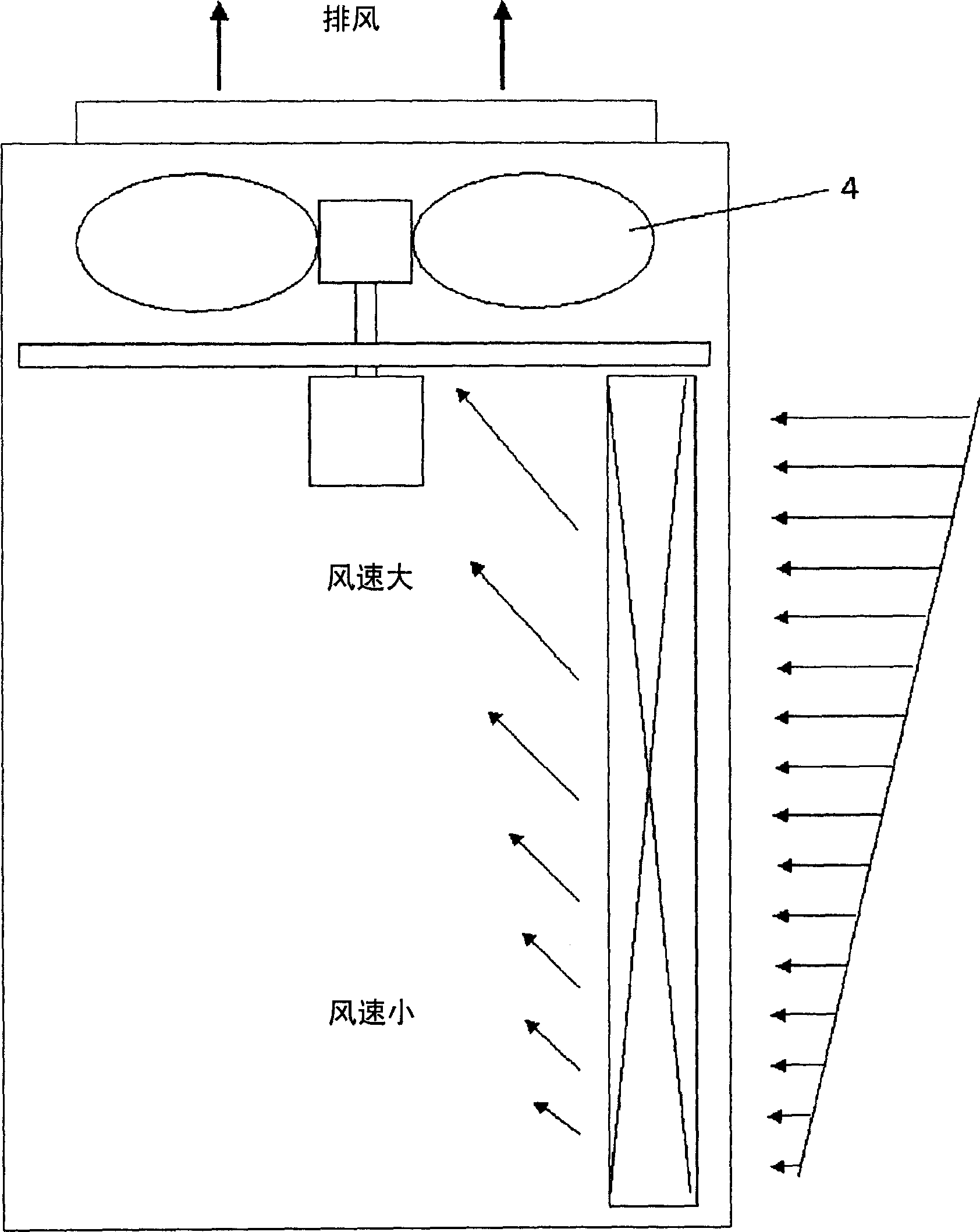
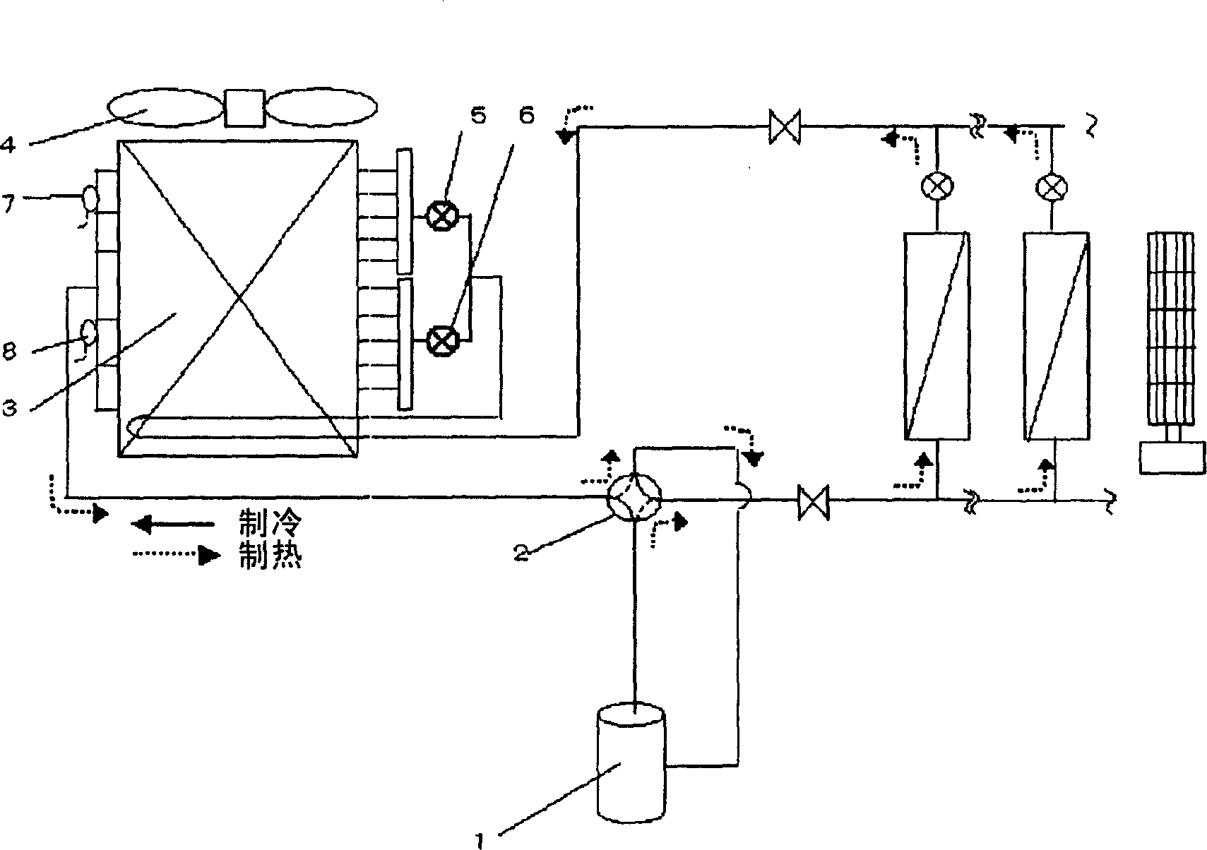
[0037] figure 1 It is a schematic structural diagram of an outdoor unit in an embodiment of the present invention, and a multi-flow air conditioner for a building is used as an example for illustration. figure 2 It is a schematic diagram of the refrigeration cycle system in the present invention.

[0038] figure 2 The refrigerating cycle system includes: a compressor 1 with adjustable power, a four-way valve 2 for switching between heating operation and cooling operation, an outdoor heat exchanger 3 , and an outdoor fan 4 . Wherein, the outdoor heat exchanger 3 is further divided into upper and lower parts, and is respectively provided with an outdoor upper expansion valve 5, an outdoor lower expansion valve 6, an outlet temperature sensor 7 at the upper part of the outdoor heat exchanger, and a lower part of the outdoor heat exchanger. Outlet temperature sensor 8.

[0039] Expansion valves 5 and 6 are driven by stepping motors operated under the control of pulse signals...

Embodiment 2

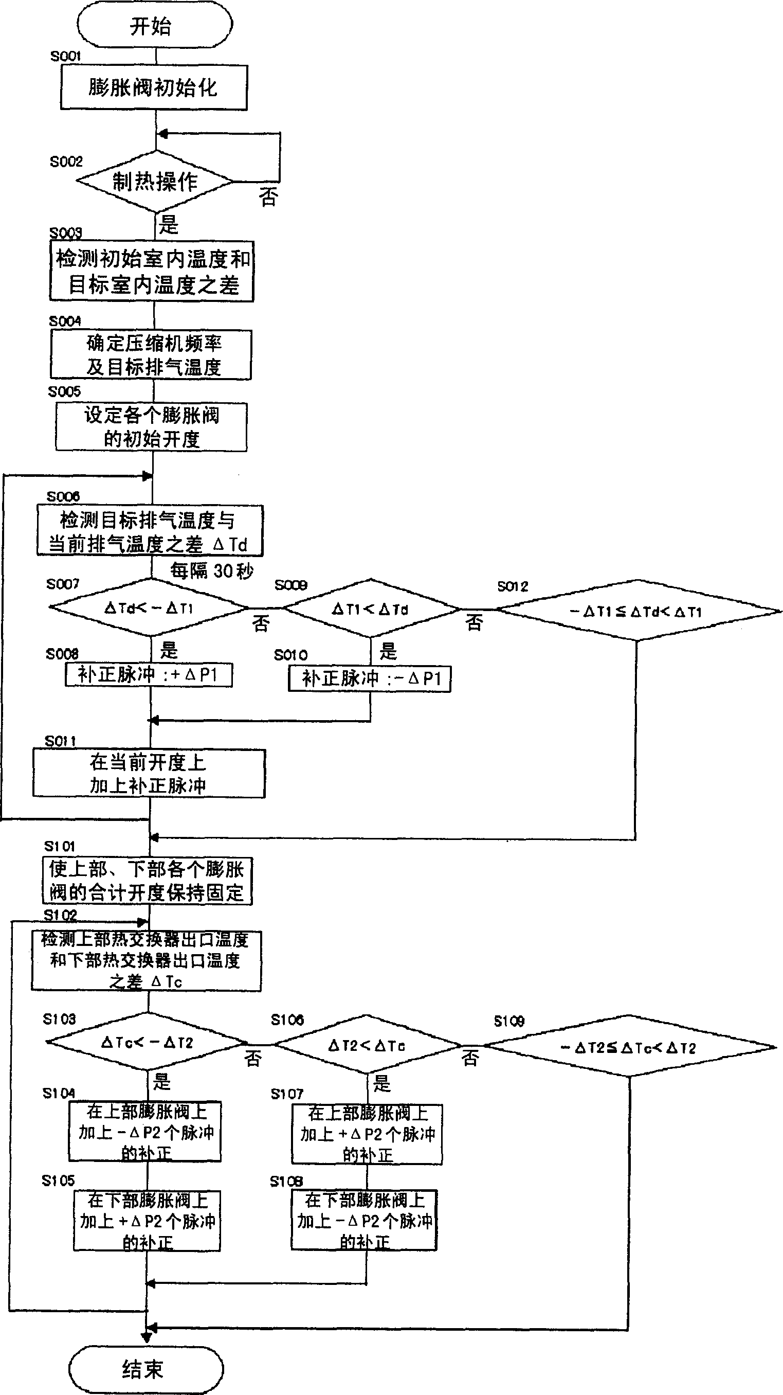
[0046] Figure 5 and Figure 6 It is the control flow chart of the air conditioner in the second embodiment of the present invention and the timing chart of the control process.

[0047] After the power is turned on, in step S001 the upper and lower expansion valves are initialized to be fully open. Next, if the heating operation is entered in step S002, then according to the difference between the initial indoor temperature and the target indoor temperature in step S003, the compressor frequency and the target discharge temperature are determined in step S004; After each expansion valve is opened up or down for the same number of pulses, it enters the target exhaust temperature control process. The specific control process is: in step S006, the difference ΔTd between the target exhaust temperature and the current exhaust temperature is detected; in step S007, when it is determined that the current exhaust temperature is lower than the target specified value ΔT1, then procee...

Embodiment 3

[0050] Figure 7 and Figure 8 It is the control flow chart of the air conditioner in the third embodiment of the present invention and the timing chart of the control process.

[0051] After the power is turned on, firstly, in step S001, the upper and lower expansion valves are initialized to be fully open. Next, if the heating operation is entered in step S002, the compressor frequency and the target discharge temperature are determined in step S004 according to the difference between the initial indoor temperature and the target indoor temperature in step S003; then, in step S005 After the upper and lower expansion valves are opened up or down for the same number of pulses, the target exhaust temperature control process is entered. The specific operation process of this control process is as follows. In step S006, the difference ΔTd between the target exhaust temperature and the current exhaust temperature is detected; if it is determined in step S007 that the current exha...


PUM


Abstract

The invention provides an air conditioner, capable of maintaining the best state of refrigeration cycle only through the control of the expansion valve. The distribution of the speed of the air current through an outdoor lateral heat exchanger is uneven, and as the flux of the refrigerant in the refrigerant flow is imbalanced and uneven under the influence of the altimeter head of the refrigerant flow, the heat exchange capacity can not be fully realized. In order to improve the adjusting ability, it is necessary to increase the size of the heat exchanger, resulting in problems of increased manufacturing costs, increased fan speed and louder noises. The outdoor heat exchanger of the invention is divided into separate parts respectively provided with expansion valves (5), (6) and heat exchangers (7), (8) at the discharging port of the outdoor heat exchanger, which respectively control the circulating volume of the refrigerant, capable of quickly stabilizing the refrigeration cycle and maximize the function of the heat exchanger.

Description

technical field [0001] The present invention relates to an air conditioner which maintains an optimum refrigerating cycle state by controlling an expansion valve. Background technique [0002] Such as Figure 13 control flow chart in Figure 14 The control timing diagram and Figure 15 As shown in the block diagram of , the existing air conditioners generally set the compressor operating frequency and the initial value of the target discharge temperature according to the difference between the initial indoor temperature and the target indoor temperature, and then maintain the optimal temperature by adjusting the opening of the expansion valve. state of the refrigeration cycle. If there is a deviation between the actual discharge temperature of the compressor and the target discharge temperature, the opening of the expansion valve is corrected to control the convergence to the target value (for an example, refer to Japanese Patent Publication No. 2001-12808 No). [0003] ...

Claims


Application Information

Patent Timeline
IPC IPC(8): F24F11/02F25B49/02
CPCF25B2400/22
Inventor 武内裕幸
Owner PANASONIC CORP
Why Eureka
Try Eureka