
Rotary blade pump

A technology of rotary vane pumps and rotors, applied in the direction of rotary piston pumps, rotary piston machines, pumps, etc., can solve the problems of fatigue fracture damage, increase the flow rate of oil in and out, and high flow rate of oil in and out, so as to avoid wear and damage of parts , Reduce the flow rate of oil in and out, increase the effect of oil flow in and out

Inactive Publication Date: 2008-03-12
王振忠 +1
View PDF9 Cites 87 Cited by
  • Summary
  • Abstract
  • Description
  • Claims
  • Application Information

AI Technical Summary

Problems solved by technology

The disadvantage of the sliding vane pump is that once the dirt enters the pump, it is easy to cause the sliding vane to be stuck, and the reciprocating friction is also easy to damage; the disadvantage of the flexible vane pump is that the blades are made of rubber, which is easy to cause fatigue, breakage and damage after long-term use. Long-term immersion in oil media such as gasoline is also prone to expansion and failure; therefore, both pumps have the defect of short service life
Specifically, the invention patent No. 97120933.2 has the following disadvantages: 1) When transporting low-density oil, it is easy to gasify and generate cavitation, and the transport efficiency is reduced
The reason is that the rotating speed of the rotor and blades is high, the flow rate of oil in and out is high and the flow rate is small, so gasoline is easy to vaporize and cause cavitation in the pump
The follow-up inner sleeve set in the stator of the original pump casing not only makes the structure of the pump complex but also cannot realize the simultaneous mixing of oil in and out of the pump in the axial and radial directions, and is not suitable for the transportation of low-density and easy-to-gasify oil media. Therefore, the application range subject to great restrictions
2) Since the adjustment and locking device of the rotor is installed in the pump, the pump cover needs to be disassembled for adjustment, which is very inconvenient to operate, and repeated disassembly may easily cause damage to parts
3) The connection method between the blade and the rotating plate and the structural design of the rotating plate itself are not reasonable enough
Since the vane pendulum shaft is press-fitted on the main body of the vane, the shaft hole is set on the rotating plate, which affects the sealing and is inconvenient to disassemble and replace; the "C" shaped hole designed on the rotating plate has a complicated manufacturing process
4) The structure of the inlet and outlet oil flow plate and the pump cover is unreasonable
The original oil inlet and outlet passages are concentrated on the front cover of the pump, which is not conducive to increasing the oil inlet and outlet flow to prevent the gasification of low-density oil medium. At the same time, the position of the oil inlet and outlet of the pump cover is fixed. Limited by space, very inconvenient
The deficiencies mentioned above seriously affect the excellent performance of this pump, which greatly limits the popularization and application.

Method used


Image

  • Rotary blade pump
  • Rotary blade pump
  • Rotary blade pump

Examples


Embodiment Construction

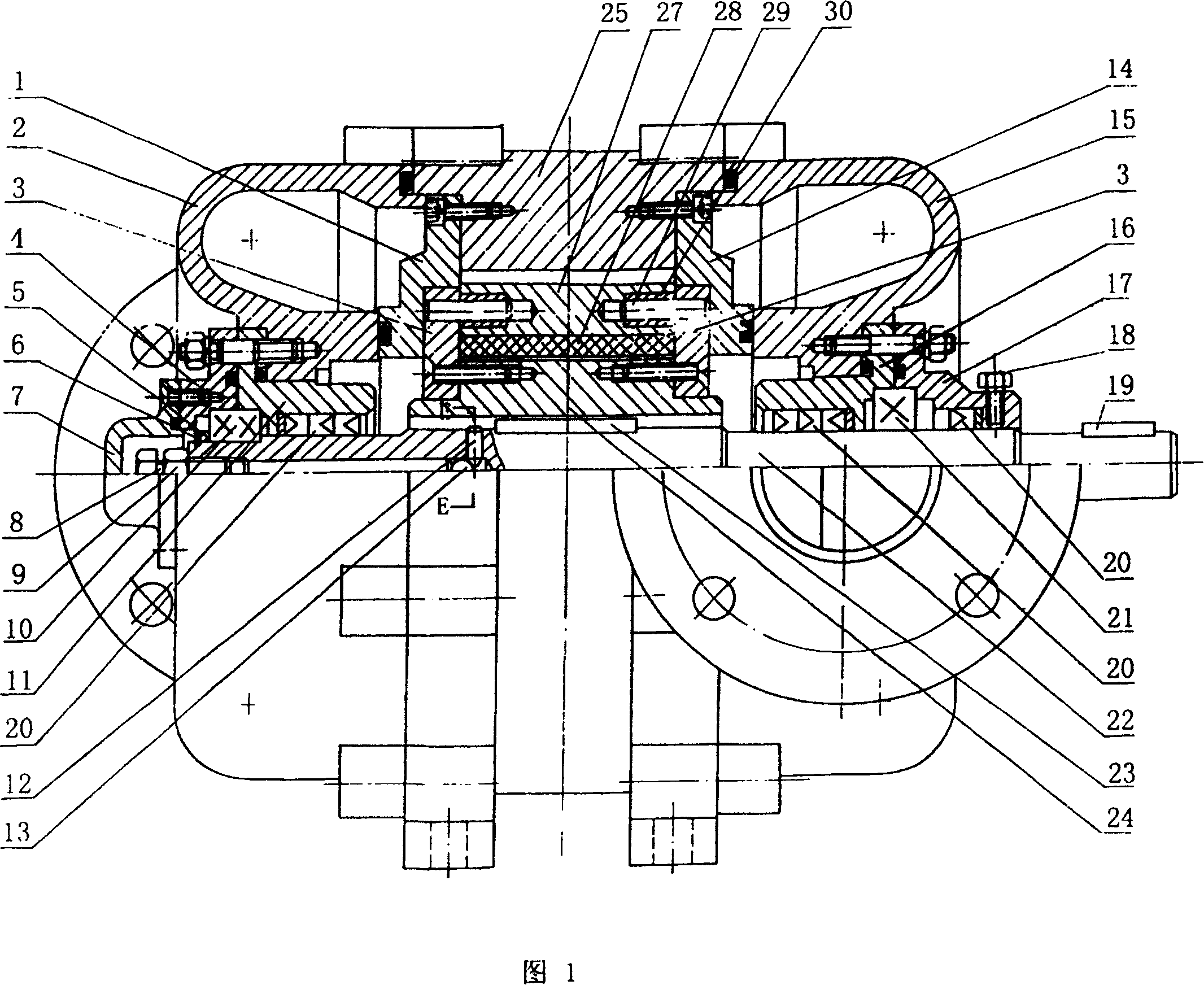
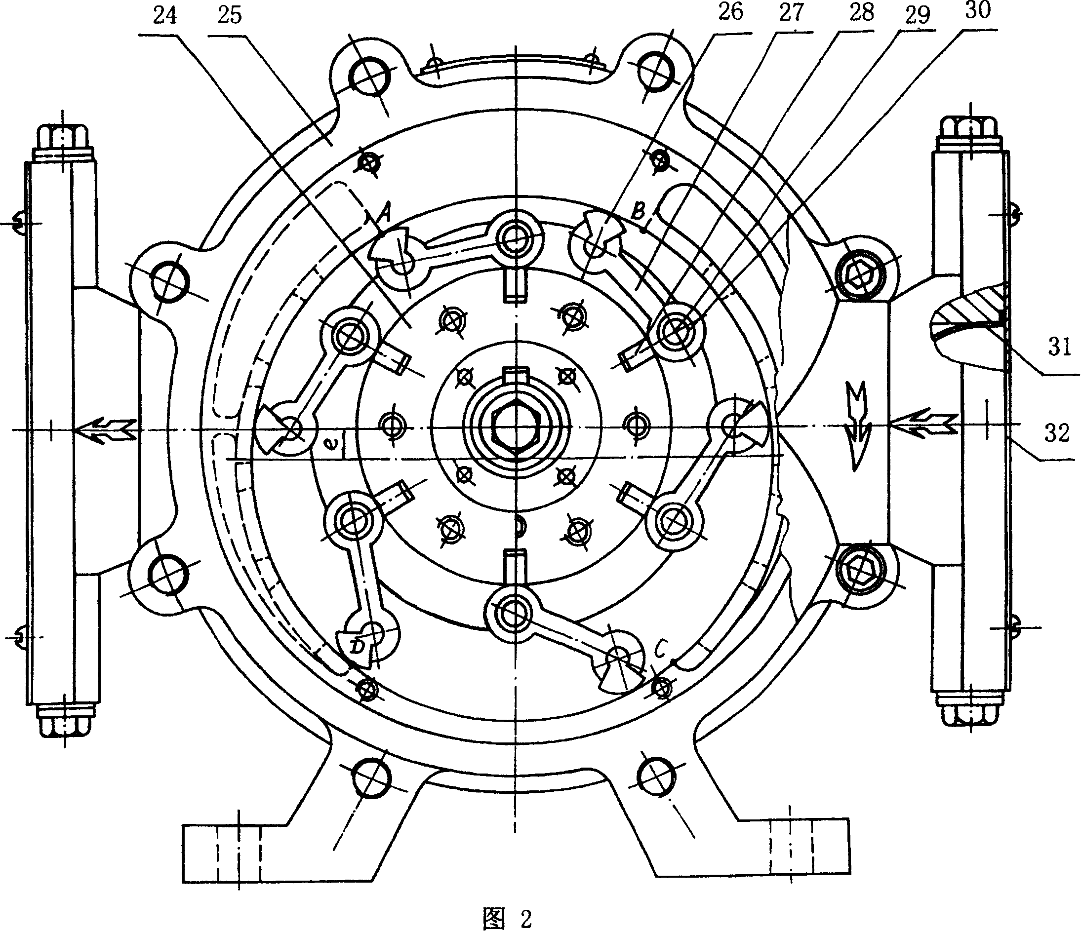
[0028] The invention consists of a stator part, a rotor part, a pump shaft part and a pump cover part. The following points are as follows:

[0029] 1. Stator part

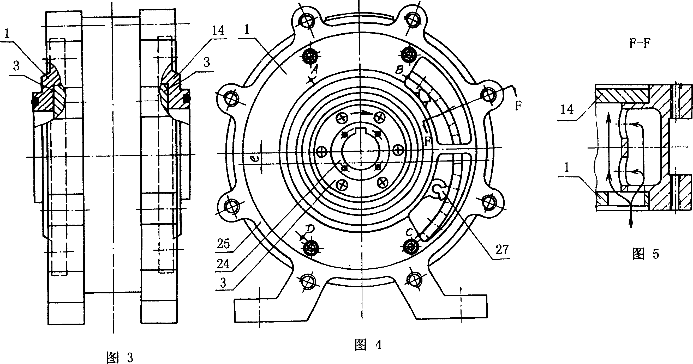
[0030] Including the pump casing stator 25, the oil inlet flow plate 1 and the oil outlet flow plate 14.

[0031] Referring to Fig. 1, Fig. 2, Fig. 3, Fig. 4, Fig. 5, Fig. 6 and Fig. 7, an oil inlet flow plate 1 is fixed on the front inner end surface of the stator 25 of the pump casing, and an oil outlet flow plate 1 is fixed on the rear inner end surface Plate 14; there is a radial oil inlet passage in the low-pressure oil inlet area of ​​the BC arc section of the pump casing stator 25, and the oil inlet passage communicates with the axial oil inlet window on the oil inlet flow plate 1; the oil inlet flow The axial oil inlet window on the plate 1 also communicates with the inner cavity of the pump casing stator 25; there is a radial oil outlet flow channel at the high pressure oil outlet area of ​​the AD arc s...


PUM


Abstract

In the invention, an inlet-outlet oil flow plate is fixed at two ends of a pump case stator. A radial inlet-outlet runner is built-up on the pump case stator to realize axial and radial inlet and outlet oil at the same time. A rotor is mounted in the internal cavity of the pump case stator and there is an offsetting e between the rotor and the ID of the pump case stator. Rotary vanes are mounted on a rotating board fixed on the two end faces of the rotor. The rotor is mounted on the pump spindle via a rotor key. A rotor locking device is assembled on the front part of the pump spindle. The inlet-outlet oil pump covers are fixed at two ends of the pump stator separately. A ring inlet-outlet oil passageway is disposed in inlet-outlet oil pump. A bearing support and sealing device is assembled on the central of the inlet-outlet oil pump cover.

Description

technical field [0001] The invention relates to a volumetric vane pump, in particular to a vane pump that can automatically open when the pump pressure exceeds the rated pressure to allow the oil to flow back and run idle. When the resistance of the vane exceeds the rated resistance, the vane will automatically open to prevent the pump from being stuck. Each vane in the pump has an overflow insurance function. It is suitable for the transportation and loading and unloading of gasoline, kerosene, diesel and other oil media, and it is also suitable for cleaning the bottom oil of oil depots, oil tanks and tankers. Background technique [0002] Positive displacement vane pumps are widely used in various oil depots and oil delivery units due to their good self-priming performance and strong adaptability. Sliding vane pumps and flexible vane pumps are currently used more. The disadvantage of the sliding vane pump is that once the dirt enters the pump, it is easy to cause the sli...

Claims


Application Information

Patent Timeline
Patent Type & Authority Patents(China)
IPC IPC(8): F04C2/44
Inventor 王振忠董惠兰
Owner 王振忠
Learn More