Total cross-section inflatable floatation machine

A flotation machine, inflatable technology, used in flotation, solid separation and other directions, can solve the problems of high cost, low sorting efficiency, high energy consumption, etc., to prolong the life of wearing parts, improve the sorting recovery rate, The effect of reducing energy consumption

Inactive Publication Date: 2011-10-12
YANTAI XINHAI MINING MACHINERY
View PDF5 Cites 7 Cited by
  • Summary
  • Abstract
  • Description
  • Claims
  • Application Information

AI Technical Summary

Problems solved by technology

[0004] In order to solve the problems of low mineral sorting efficiency, high energy consumption and high co

Method used


Image

  • Total cross-section inflatable floatation machine
  • Total cross-section inflatable floatation machine
  • Total cross-section inflatable floatation machine

Examples


Embodiment 1

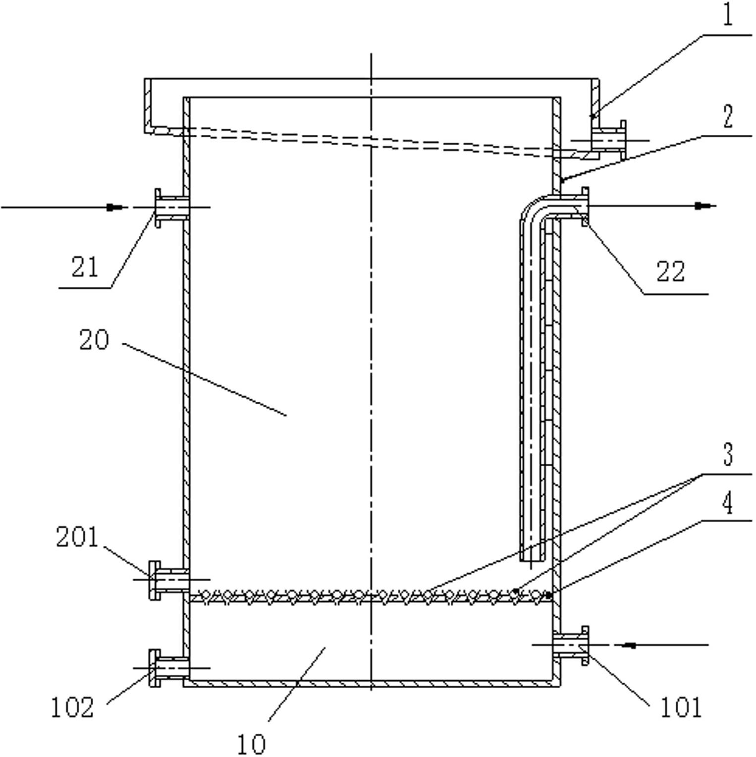
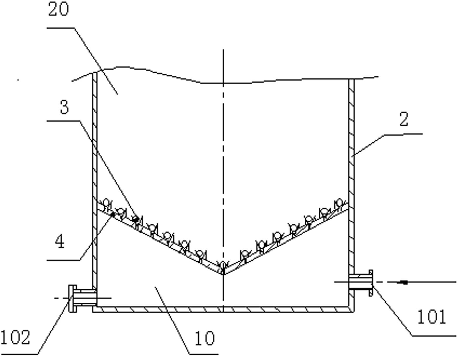
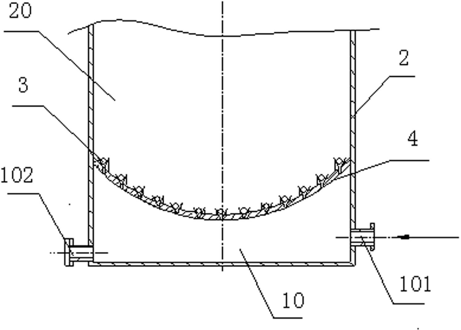
[0044] Such as figure 1As shown, a full-section inflatable flotation machine includes a flotation cell 2 and a foam overflow mechanism installed on the top of the flotation cell 2, and the upper side wall of the flotation cell 2 is provided with a pulp inlet 21 and a pulp outlet 22. A one-way valve mounting plate 4 is installed at the bottom of the flotation cell 2, and the shape of the one-way valve mounting plate 4 matches the cross-sectional shape of the bottom of the flotation cell 2, that is, the outer peripheral shape of the one-way valve mounting plate 4 It is the same as the cross-sectional shape of the bottom of the flotation cell 2, so that the flotation cell 2 is divided to form a slurry chamber 20 and an air chamber 10 located below the slurry chamber 20, and the check valve mounting plate 4 is uniformly and densely distributed. One-way valve 3, the side of the bottom of the slurry chamber 20 is provided with an ore discharge port 201, and the slurry outlet 22 is c...

Embodiment 2

[0053] Such as Figure 8 As shown, the full-section inflatable flotation machine of the present invention can add a stirring device when necessary, and the stirring device 5 includes a motor 51, a transmission mechanism 52, a main shaft 53 and an impeller 54, and the top of the flotation cell 2 is provided with a support 6, The foam tank 1 is installed below the support 6, the top of the main shaft 53 is installed on the support 6, the impeller 54 is installed on the bottom of the main shaft 53, and the motor 51 drives the main shaft 53 to rotate through the transmission mechanism 52, thereby driving the impeller 54 to rotate.

[0054] The impeller 54 of the stirring device is not responsible for air suction, dispersing air bubbles, and stirring the ore pulp. Its purpose is only to assist in the further mixing of liquid, solid, medicine, and air bubbles in the ore pulp. Therefore, the linear speed of the impeller 54 is reduced, and the required The input power is greatly reduc...

Embodiment 3

[0056] Such as Figure 9 As shown, according to actual needs, corresponding bubble dampers 7 can be added inside the flotation machine cell body 2, such as Figure 10 As shown, the foam damper 7 is composed of four damping plates 71 and a support plate 72 connecting the four damping plates 71. The damping plates 71 are closely arranged with a plurality of through holes 710, and the four damping plates 71 pass through The support plate 72 is installed in the cell body 2 of the flotation machine. The through hole 710 may be a round hole or a square hole. The shape of the damping plate 71 matches the cross-sectional shape of the cell body 2 of the flotation cell.

[0057] The foam damper 7 can change the straight-line rising route of the bubbles and prevent small bubbles from agglomerating into large bubbles, prolong the rising time of the bubbles at the same height of the flotation machine tank and make the bubbles fully contact with the pulp, or no bubble damping can be provi...


PUM


Abstract

The invention relates to a total cross-section inflatable floatation machine, comprising a flotation tank and a foam overflow mechanism arranged at the top of the flotation tank, wherein the tank body of the flotation tank is provided with an ore pulp inlet and an ore pulp outlet, the bottom of the tank body of the flotation tank is provided with a check valve mounting plate, and the shape of the check valve mounting plate is matched with that of the cross section of the bottom of the tank body of the flotation tank, thus the tank body of the flotation tank is divided into a pulp bearing chamber and an air chamber arranged below the pulp bearing chamber, one side of the bottom of the pulp bearing chamber is provided with an ore discharge port, one side of the air chamber is provided with an air inlet, and multiple check valves are uniformly distributed on the check valve mounting plate. The total cross-section inflatable flotation machine provided by the invention has a simple structure and is convenient to maintain, the ore dressing recovery percentage is improved, the energy consumption is reduced, gas is fully utilized, the chemical usage is reduced, the life of a quick-wear part is prolonged, the flotation process stage is shortened, and the equipment cost and investment of capital construction are reduced.

Description

technical field [0001] The invention relates to a kind of mineral processing equipment, in particular to an inflatable flotation machine for metal ore or nonmetal ore or coal. Background technique [0002] In the flotation machine, the ore pulp treated with chemicals is agitated or self-absorbed to make some of the ore particles selectively attach to the air bubbles. Because the integrated density of the air bubbles attached to the minerals is small, the air bubbles float to the surface of the ore pulp. It is scraped out to form a foam product, and the rest is retained in the slurry, so as to achieve the purpose of separating minerals. [0003] Commonly used flotation machines are mostly divided into mechanical agitation self-suction air type, mechanical agitation inflatable type, inflatable type and other categories. However, regardless of the mechanical stirring self-suction air type or the inflatable flotation machine, it is necessary to set a corresponding rotating st...

Claims


Application Information

Patent Timeline
IPC IPC(8): B03D1/16
CPCB03D1/1481B03D1/242B03D1/245Y02P70/10
Inventor 张云龙
Owner YANTAI XINHAI MINING MACHINERY
Why Eureka
Try Eureka