Light-emitting diode packaging structure and method for making same

A technology of light-emitting diodes and packaging structures, applied in electrical components, electrical solid-state devices, circuits, etc., can solve the problems of SMD LED luminous efficiency and poor quality, abnormal SMD LEDs, and difficulty in making reflective grooves, etc., so as to be suitable for mass production , good heat dissipation, and simplified manufacturing process

Inactive Publication Date: 2008-04-16
IND TECH RES INST
View PDF2 Cites 1 Cited by
  • Summary
  • Abstract
  • Description
  • Claims
  • Application Information

AI Technical Summary

Problems solved by technology

[0002] Traditional surface-mount light-emitting diode (SMD LED, hereinafter only abbreviated) packages are mainly divided into bracket type and circuit board type. The bracket type uses metal brackets and heat-resistant plastic materials to form a slot for injection molding to serve as a light-emitting diode. The chip is fixed on the base, while the circuit board type uses a composite material circuit board as the substrate, and then carries out actions such as solid crystal, wire bonding, and glue sealing on the slot or substrate; these two methods have some common disadvantages. One is that the temperature resistance is not enough, especially when the SMD LED is bonded with other circuit boards, it needs to go through a high-temperature furnace (about 250-300°C), which will cause abnormal defects in the SMD LED. The second is that the heat dissipation is not good. It is usually accompanied by the accumulation of heat, especially for LEDs with optical power
Temperature rise will have a negative impact on the luminous efficiency and quality of SMD LEDs. In addition, it is basically difficult to make reflective grooves in traditional SMD LED processes when miniaturized.
[0003] The Taiwanese patent No. 495939 proposes a packaging method for light-emitting diodes, such as figure 1 As shown, it mainly uses a silicon chip as the packaging substrate. The crystal surface of the silicon substrate 8 has a specific crystallographic direction, and grooves can be etched, and the through-hole electrodes 13 are made on the back of the silicon substrate 8, and the insulating layer is formed by oxidation treatment. Layer 15 is then plated with reflective layer 16 and electrode layers 17, 18, thus forming a base for the manufacture of LED chips 3, and then performing steps such as die bonding, wire bonding, sealing, and cutting to complete light emission. Finished diodes; this method has the advantages of high temperature resistance, easy fabrication of reflection grooves, and good heat dissipation, which greatly improves the traditional SMD LED packaging method. However, it must enter and exit the furnace tube many times during the process to grow the required insulating layer. , the production process is very complicated, therefore, it is necessary to seek a packaging method for light-emitting diodes that is simpler and can simultaneously improve temperature resistance, heat dissipation, and the production of reflective grooves.

Method used


Image

  • Light-emitting diode packaging structure and method for making same
  • Light-emitting diode packaging structure and method for making same
  • Light-emitting diode packaging structure and method for making same

Examples


Embodiment Construction

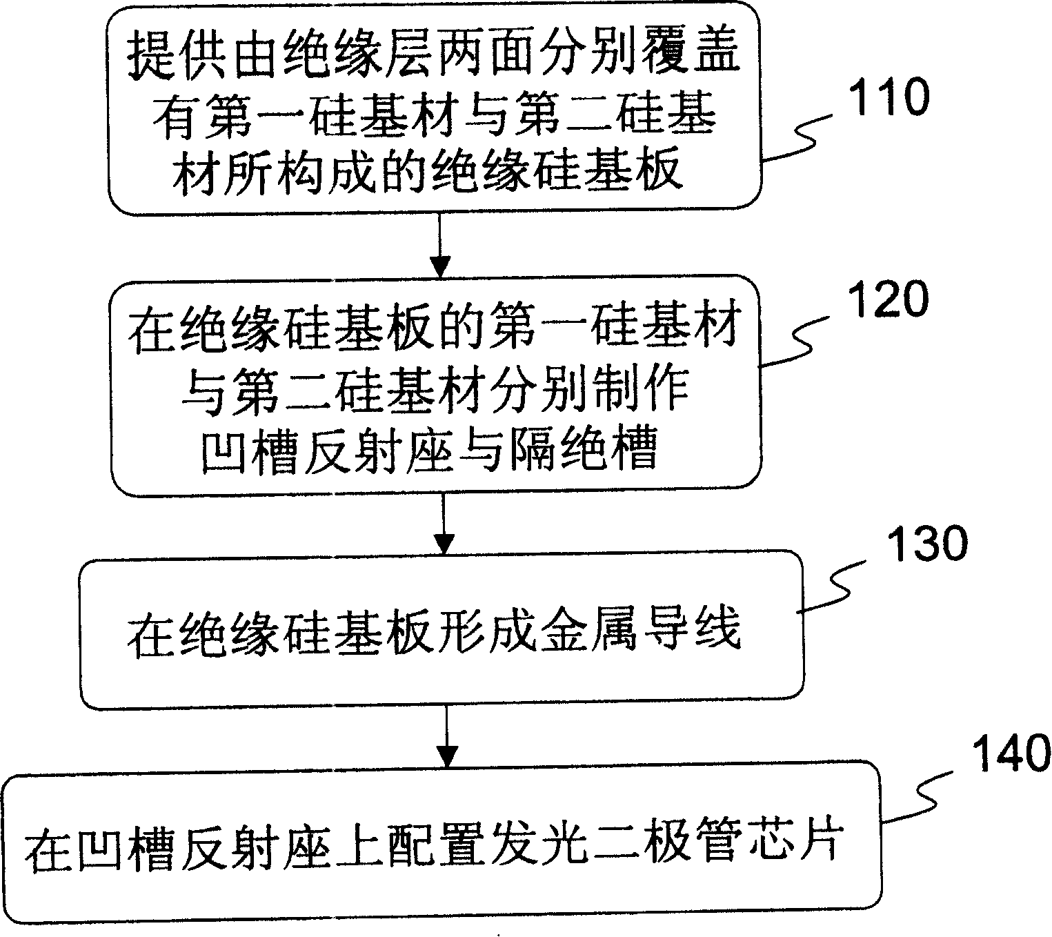
[0047] The schematic flow chart of the first embodiment of the present invention is as follows figure 2 As shown, the steps include:

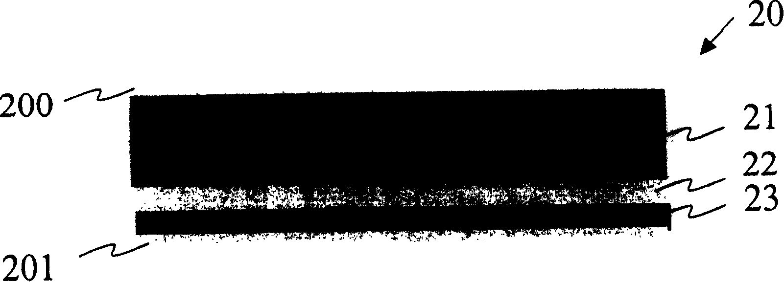
[0048] First, provide an insulating silicon substrate composed of a first silicon substrate and a second silicon substrate on both sides of the insulating layer (step 110);

[0049] Then, fabricate groove reflection seats and isolation grooves on the first silicon base material and the second silicon base material of the insulating silicon substrate respectively (step 120);

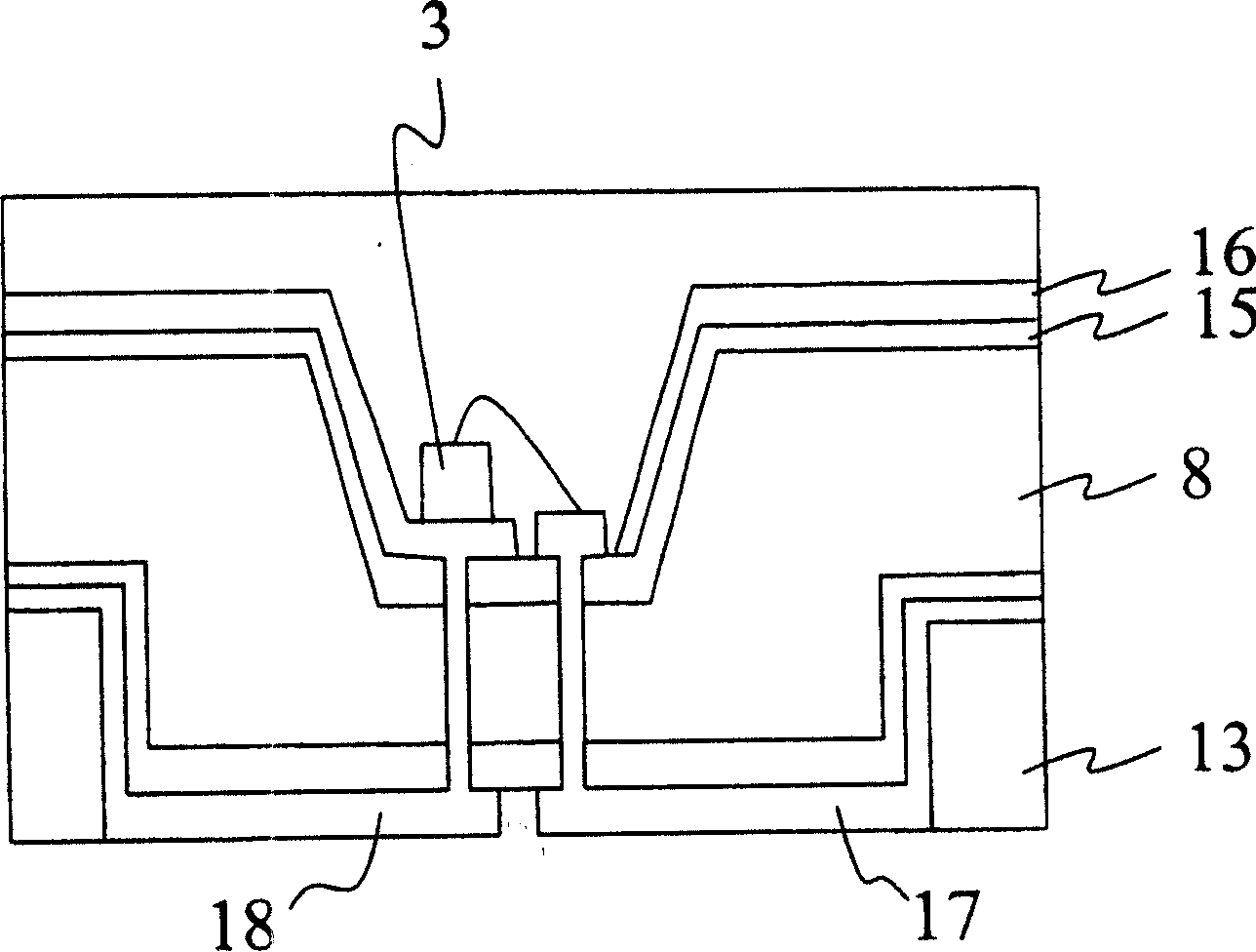
[0050] forming metal wires on a silicon-on-insulator (SOI) substrate (step 130), for electrical connection between the light-emitting diode chip and the first silicon substrate and the second silicon substrate of the silicon-on-insulator substrate;

[0051] Arrange light-emitting diode chips on the groove reflective seat (step 140), and electrically connect to the positive and negative electrodes externally connected to the insulating silicon substrate respectively throu...


PUM


Abstract

The invention discloses a manufacture method for package structure of LED. Wherein, using insulated silicon with insulation layer between two layers of silicon material as package substrate; preparing groove reflection base and isolation slot to divide positive and negative electrodes of substrate on two layers of silicon material respectively and multiple metal wires to connect said silicon material; then, arranging the LED chip on said base and connecting to said electrodes by metal wires. This invention improves heat-resistant and heat dissipation properties.

Description

technical field [0001] The invention relates to a light-emitting diode packaging structure and a manufacturing method thereof, in particular to a light-emitting diode packaging structure with insulating silicon as a packaging substrate and a manufacturing method thereof. Background technique [0002] Traditional surface-mount light-emitting diode (SMD LED, hereinafter only abbreviated) packages are mainly divided into bracket type and circuit board type. The bracket type uses metal brackets and heat-resistant plastic materials to form a slot for injection molding to serve as a light-emitting diode. The chip is fixed on the base, while the circuit board type uses a composite material circuit board as the substrate, and then carries out actions such as solid crystal, wire bonding, and glue sealing on the slot or substrate; these two methods have some common disadvantages. One is that the temperature resistance is not enough, especially when the SMD LED is bonded with other cir...

Claims


Application Information

Patent Timeline
Patent Type & Authority Patents(China)
IPC IPC(8): H01L33/00H01L33/48
CPCH01L2224/48091H01L2224/48227H01L2924/181H01L2924/00014H01L2924/00012
Inventor 陈明鸿温士逸郭武政陈炳儒翁瑞坪李孝文
Owner IND TECH RES INST
Why Eureka
Try Eureka