Eureka AIR delivers breakthrough ideas for toughest innovation challenges, trusted by R&D personnel around the world.

Image forming device

An image and image carrier technology, which is applied in the fields of electrical recording technology using charge graphics, equipment for using electrical recording technology using charge graphics, and electrical recording technology, can solve the problem of not being able to obtain sufficient light-shielding effect, increasing the number of components, and impossibility Sufficiently prevent problems such as low-cost reliability, simple configuration, and improved productivity

Inactive Publication Date: 2008-04-30
COPYER
View PDF6 Cites 0 Cited by
  • Summary
  • Abstract
  • Description
  • Claims
  • Application Information

AI Technical Summary

Problems solved by technology

However, when other parts such as a light-shielding plate are arranged, there is a problem that a sufficient light-shielding effect cannot be obtained due to space constraints in the main body of the device, and the product cost increases due to an increase in the number of parts.
Moreover, even if the arrangement of components inside the device body is optimized, it is impossible to sufficiently prevent the reflected light from reaching the image carrier as long as the reflected light in the paper conveying path extending from the paper feeding opening is not blocked.

Method used


Image

  • Image forming device
  • Image forming device
  • Image forming device

Examples


Embodiment Construction

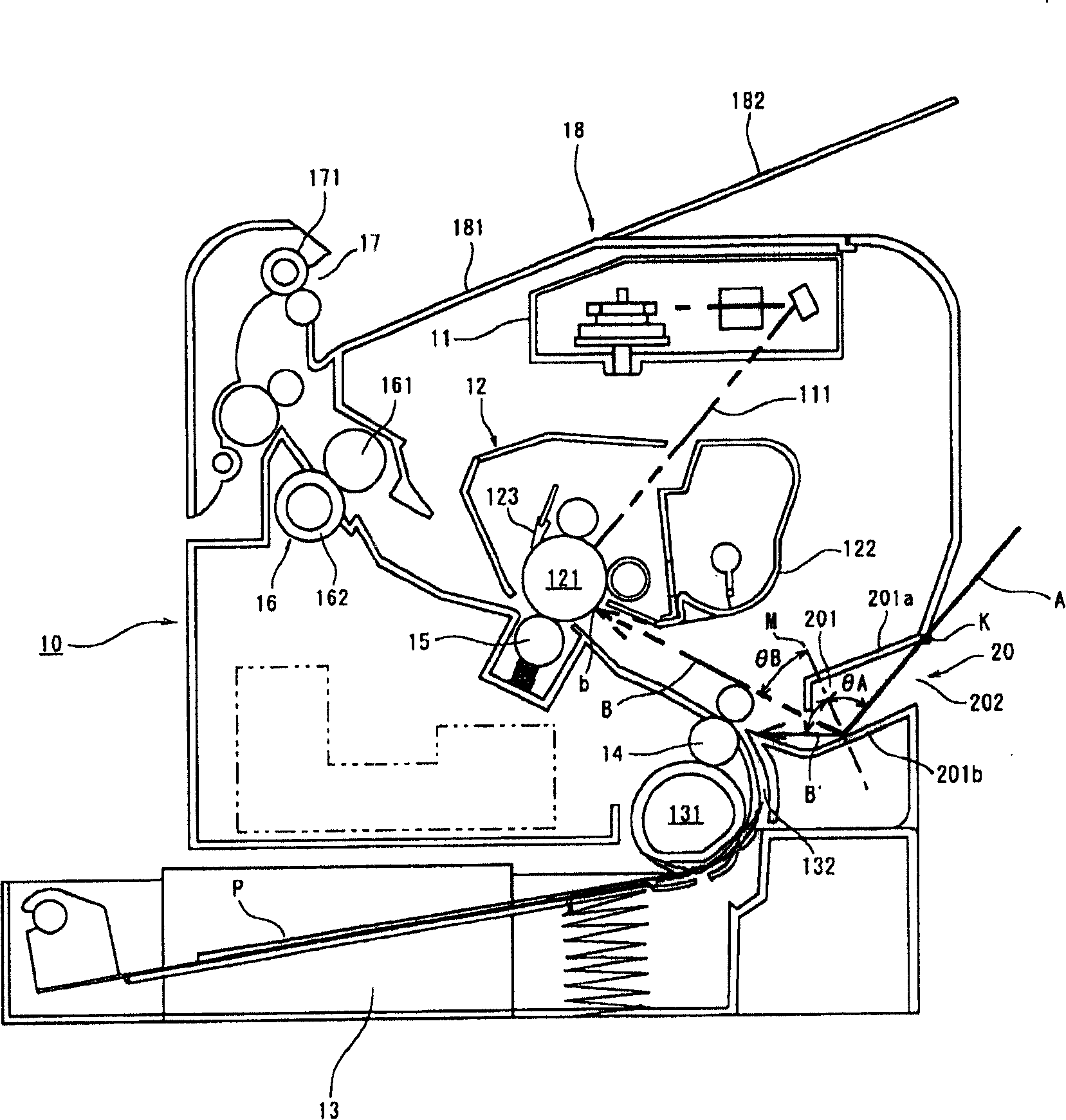
[0024] Hereinafter, embodiments of the present invention will be described in detail based on the drawings, but prior to this, an overview of the overall configuration of an image forming apparatus will be given by taking a laser printer as an example.

[0025] exist figure 1 In the laser printer 10 shown, for example, image information sent from an external computer is formed into light modulation information 111 by a laser light emitting writing unit 11 through an image controller (not shown), and is stored in a process box 12. The photosensitive drum 121 as an image carrier is imaged in a dot shape, and the light spot is scanned back and forth in the axial direction (main scanning direction) of the photosensitive drum 121 to form an electrostatic latent image corresponding to the image on the photosensitive drum 121 . Then, a developer (toner) is supplied to the electrostatic latent image on the photosensitive drum 121 from a developing device 122 integrally provided in th...


PUM


Abstract

In an auxiliary sheet feeder (20) that feeds a recording medium (P), fed from the outside via a paper feed opening (202) provided in a device body, into the sheet carrying route (132) of a main sheet feeder (13), a sheet carrying path (201) extending from the opening (202) up to the sheet carrying route (132) is formed so that a disturbance light (A) intruding via the opening (202) is reflected in a direction other than an advancing direction toward an image carrier or shielded to thereby remove disturbance by a disturbance light (A) on a latent image written on the image carrier and produce a good image, whereby it is possible to obtain a high-quality image by a simple construction.

Description

technical field [0001] The present invention relates to an image forming apparatus in which a paper feeding opening for feeding a recording medium is provided in an apparatus main body. Background technique [0002] Generally, in various image forming apparatuses such as electrophotographic copiers and printers, a paper feeding device composed of a paper feeding cassette capable of loading a plurality of recording media is arranged, and the recording media output from the paper feeding device are conveyed by the paper feeding device. It is conveyed through the path, and thus is sent to the transfer area of ​​an image carrier such as a photosensitive drum where an electrostatic latent image is formed. [0003] In such a paper feeding device, in particular, for the purpose of feeding special recording media such as heavy paper other than normal recording paper, postcards, envelopes, etc., there are cases where an opening for feeding paper is provided on the main body of the de...

Claims


Application Information

Patent Timeline
Patent Type & Authority Patents(China)
IPC IPC(8): G03G15/00G03G21/00
CPCG03G15/6502G03G15/00G03G15/1615G03G21/00
Inventor 今泉和明
Owner COPYER
Why Eureka
Eureka Blog
Learn More