Torque vibration damper

A technology of torsional vibration and damper, applied in vibration suppression adjustment, spring/shock absorber, mechanical equipment, etc., can solve problems such as fluctuation

Inactive Publication Date: 2008-05-28
LUK LAMELLEN & KUPPLUNGSBAU BETEILIGUNGS KG
View PDF6 Cites 0 Cited by
  • Summary
  • Abstract
  • Description
  • Claims
  • Application Information

AI Technical Summary

Problems solved by technology

The friction torque generated by the friction device is therefore subject to strong fluctuations, which is undesirable when working with torsional vibration dampers

Method used


Image

  • Torque vibration damper
  • Torque vibration damper
  • Torque vibration damper

Examples


Embodiment Construction

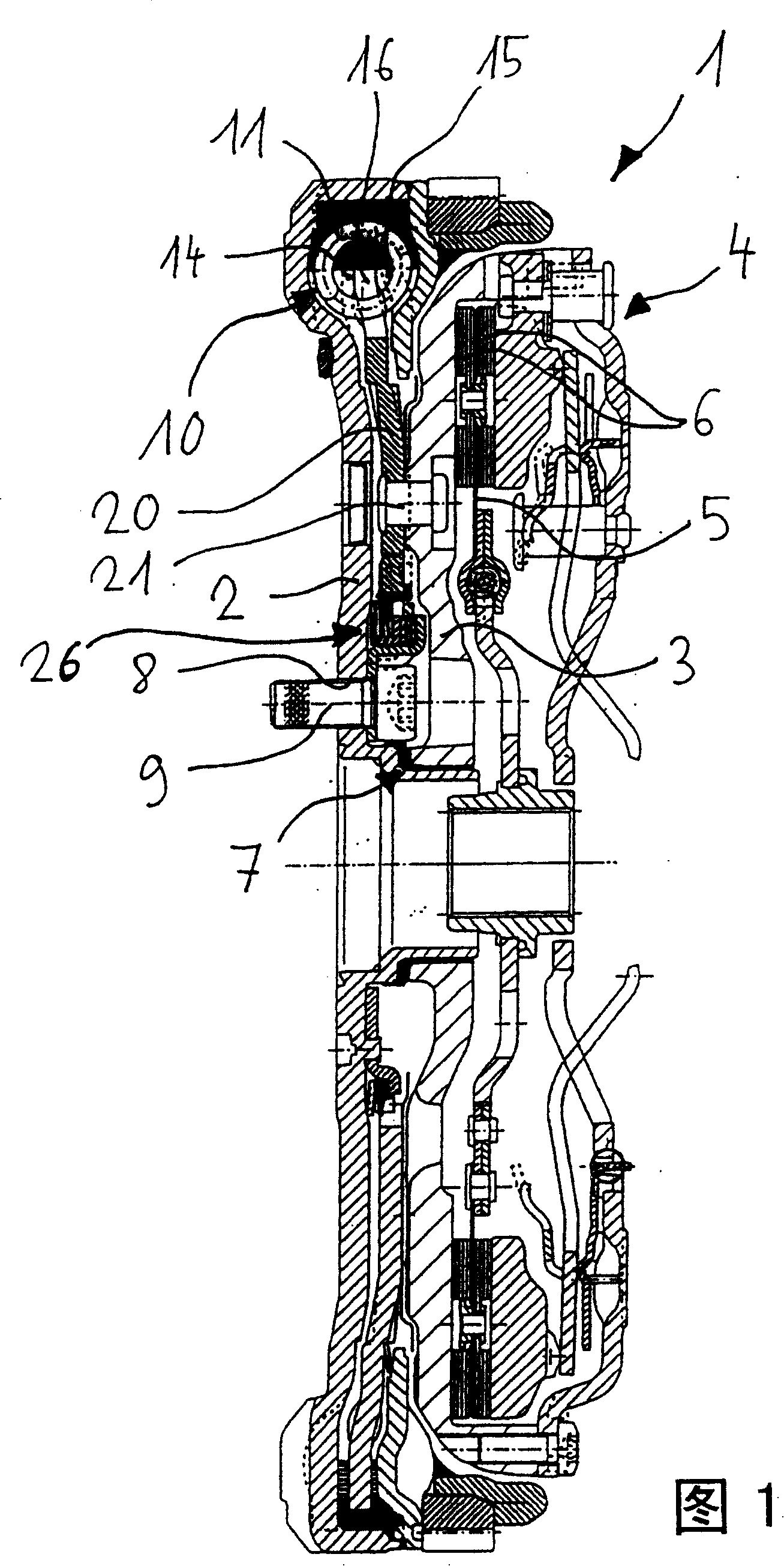
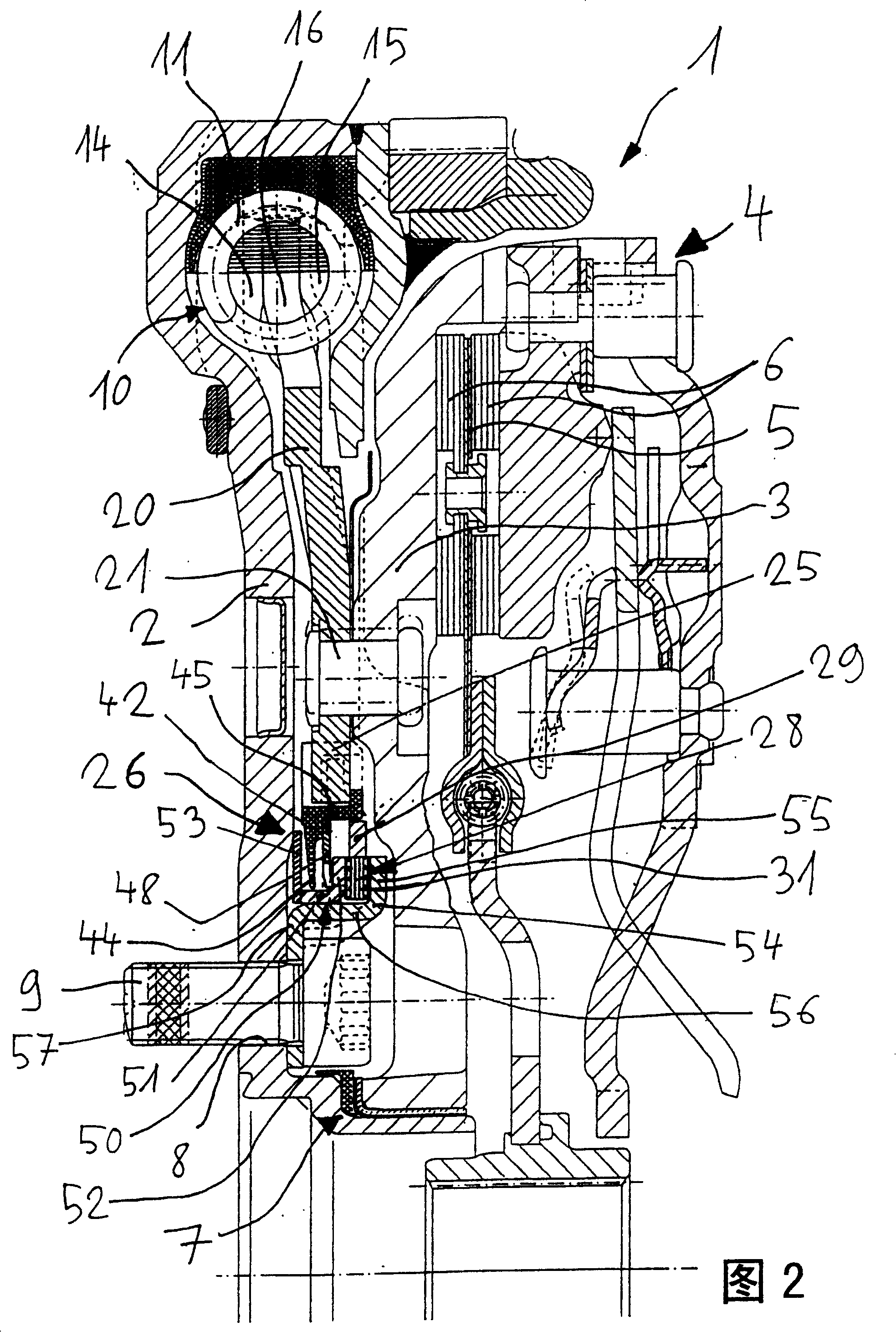
[0027] The torsional vibration damper shown in Figure 1 constitutes a split flywheel 1 having a first or primary flywheel mass 2 and a second or secondary flywheel mass 2 fixable on the output shaft (not shown) of an internal combustion engine. Grade flywheel quality 3. A friction clutch 4 can be attached to the second flywheel mass 3 with a clutch disk 5 interposed therebetween, by means of which a (also not shown) transmission input shaft can be engaged or disengaged. On the clutch disc 5 are mounted friction linings 6 which are loaded with pressure when the clutch is engaged. The function of the friction clutch 4 is assumed to be known and will therefore not be explained further.

[0028] The flywheel masses 2 and 3 are rotatably supported relative to one another via a support structure 7 which, in the illustrated embodiment, is arranged radially inside holes 8 for passing fixing screws 9 for The first flywheel mass 2 is mounted on the output shaft of the internal combust...


PUM


Abstract

The torsional vibration damper has two flywheel masses rotatable against the resistance of at least one damping device and friction unit. The friction unit has at least one first support unit which is connected and torsionally fixed to the primary flywheel mass, and including a coupling device which is connected and torsionally fixed to the secondary flywheel mass and coupled to a support component which has several friction elements. The torsional vibration damper has a first spring bearing by one side on the primary flywheel mass and by the other side bearing on the support unit which in turn bears against the support component for the friction elements.

Description

technical field [0001] The invention relates to a torsional vibration damper, in particular a split flywheel having at least two flywheel masses rotating against the resistance of at least one damping means and a friction means, these flywheel masses are called primary and secondary flywheel quality. Background technique [0002] When using conventional torsional vibration dampers, especially a split flywheel with at least two flywheel masses that can rotate against the resistance of at least one damping device and a friction device, tests within the scope of the present invention have shown that: The coefficient of friction of the friction device changes greatly during operation, especially when the torsional vibration damper is started. The friction torque generated by the friction device is therefore subject to strong fluctuations, which is undesirable when the torsional vibration damper is in operation. Contents of the invention [0003] Therefore the object of the p...

Claims


Application Information

Patent Timeline
Patent Type & Authority Patents(China)
IPC IPC(8): F16F15/139F16F15/131F16F15/134
CPCF16F15/13178F16F15/134F16F15/139
Inventor 约翰·耶克尔哈特穆特·蒙德
Owner LUK LAMELLEN & KUPPLUNGSBAU BETEILIGUNGS KG
Why Eureka
Try Eureka