Adhesive layer removal device for adhesive tape and thickness gauge using the device
A technology of glue coating and adhesive tape, applied in measuring devices, cleaning methods using tools, instruments, etc., can solve the problems of testers' health hazards, fatigue and boredom, and low efficiency, so as to improve labor efficiency, improve accuracy, The effect of simple and convenient operation
- Summary
- Abstract
- Description
- Claims
- Application Information
AI Technical Summary
Problems solved by technology
Method used
Image
Examples
Embodiment 1
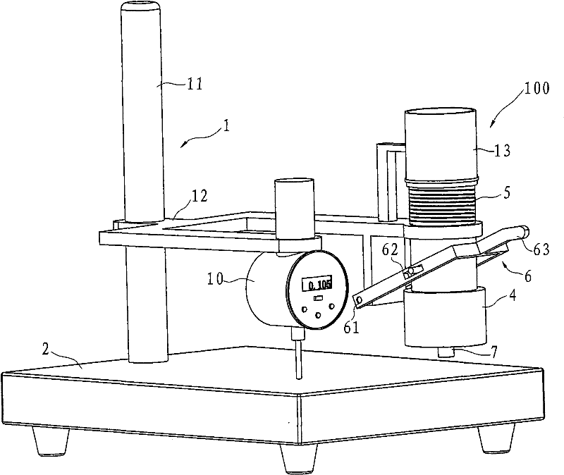
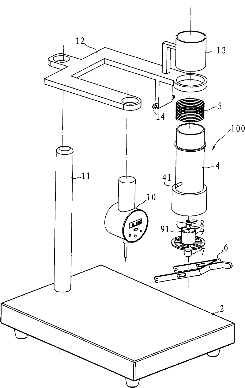
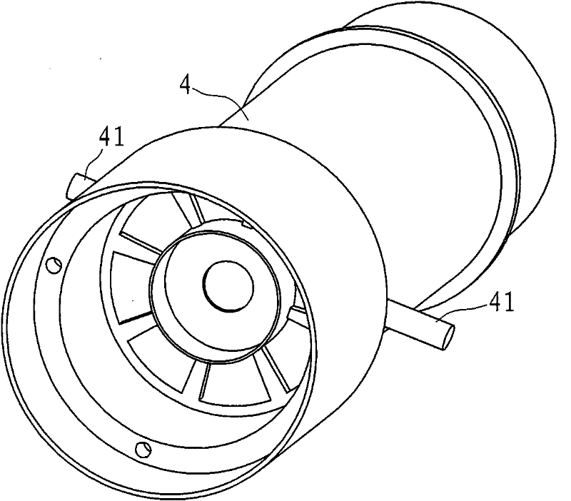
[0040] Example 1, such as figure 1 , figure 2 and image 3 As shown, the thickness gauge in this embodiment includes a base 2 , a bracket 1 , a thickness measuring device 10 and a glue layer removing device 100 .
[0041] The base 2 has a thickness measuring table, the support 1 includes a column 11 and a horizontal frame 12, the bottom of the column 11 is arranged on the base 2, the horizontal frame 12 is arranged on the column and has a certain distance from the thickness measuring table. The thickness measuring device 10 is arranged on the horizontal frame 12 and is opposite to the thickness measuring platform.
[0042] The glue layer removing device 100 is arranged on the horizontal frame 12 , and the glue layer removing device 100 includes a motor 9 , a fan 8 , a barrel 4 , a wiping head 7 and a wrench mechanism 6 . The motor 9 has an output shaft 91 , the wiping head 7 and the fan 8 are respectively located at two ends of the output shaft 91 , and the output shaft 91...
Embodiment 2
[0047] Example 2, such as Figure 4 and Figure 5 As shown, the motor 9 in this embodiment is arranged on one side of the barrel 4 , and the fan 8 is driven by another independent fan motor 81 , and both the fan 8 and the fan motor 81 are located inside the barrel 4 . Other structures are the same as in Embodiment 1. In this embodiment, the output shaft is parallel to the thickness measuring table, the wiping head 7 rotates, and the wiping head 7 removes the adhesive layer by rubbing the cylindrical arc surface on the side.
Embodiment 3
[0048] Example 3, such as Figure 6 and Figure 7 As shown, the wiping head 7 in this embodiment is connected to the output shaft through a transmission mechanism. The transmission mechanism is located in the cylinder body 4. The transmission mechanism includes a connecting block 94, a slide block 93 and a connecting rod 92. The connecting block 94 has a horizontally arranged chute 95. The first end of the slide block 93 is connected to the motor output shaft 91 and can slide Set in the chute 95 of the connecting block, the connecting rod 92 is set on the connecting block 94 and can move back and forth driven by the sliding block 93 , and the wiping head 7 is arranged at the end of the connecting rod 92 .
[0049]Wiping head 7 comprises wiping roller grain 73, connecting arm 72 and button spring 75, and wiping rolling grain 73 is two, is used to directly act on adhesive tape coating layer, and connecting arm 72 is also two for wiping rolling grain 73, each The first end of t...
PUM
 Abstract
Description
Claims
Application Information
 - R&D
- Intellectual Property
- Life Sciences
- Materials
- Tech Scout
- Unparalleled Data Quality
- Higher Quality Content
- 60% Fewer Hallucinations
Browse by: Latest US Patents, China's latest patents, Technical Efficacy Thesaurus, Application Domain, Technology Topic, Popular Technical Reports.
© 2025 PatSnap. All rights reserved.Legal|Privacy policy|Modern Slavery Act Transparency Statement|Sitemap|About US| Contact US: help@patsnap.com


