
Measuring method for precision parallelism

A measurement method and parallelism technology, applied in the field of measurement, can solve problems such as limiting IC processing accuracy, achieve the effect of improving processing level and integration, achieving improvement and easy operation

Inactive Publication Date: 2008-05-28
SHENYANG INST OF AUTOMATION - CHINESE ACAD OF SCI
View PDF4 Cites 3 Cited by
  • Summary
  • Abstract
  • Description
  • Claims
  • Application Information

AI Technical Summary

Problems solved by technology

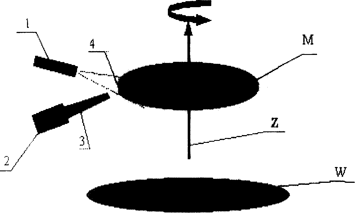
Traditional methods using precision distance sensors (such as capacitance method, optical ranging method, electromagnetic method, etc.) can only measure the distance between the measured plane (such as a wafer, defined as M) and the reference plane (such as a template installation plane, defined as W). The relative distance of a limited number of positions, when the flatness of the wafer surface cannot be higher than the required measurement accuracy, the measurement data of these measurement points cannot correctly reflect the parallel relationship between M and W at a higher technical requirement level, thus Limits the precision of IC processing

Method used


Image

  • Measuring method for precision parallelism
  • Measuring method for precision parallelism
  • Measuring method for precision parallelism

Examples


Embodiment Construction

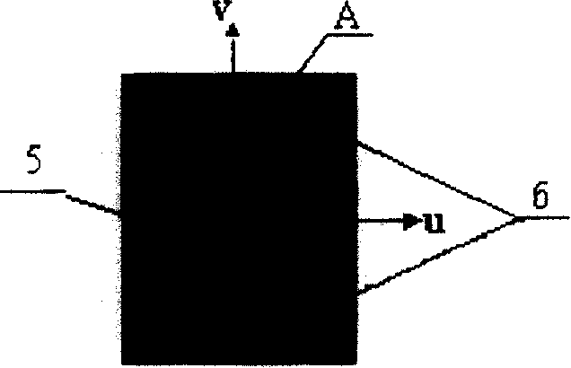
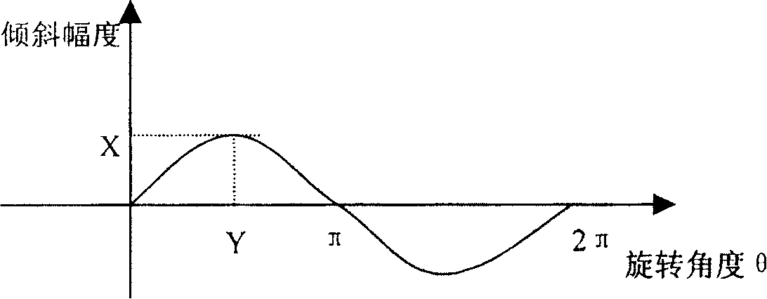
[0014] Suppose M is the object to be measured, W is the reference plane, which is located below the reference plane W, and Z is the rotation axis. The object M to be measured is installed on a platform with a rotation axis Z, which can rotate around the rotation axis Z. The rotation axis Z and The reference plane W is vertical; a bundle of illumination sources and a camera (a CCD camera is used in this embodiment) are used as the measuring device, so that the camera lens is aimed at the side of the object M to be measured, and the light source projected on the side of the object M to be received Reflective imaging, that is, the reflected light imaging projected on the side of the measured object is generated on the camera; the horizontal axis u and the vertical axis v are the image coordinate system after imaging, and the origin is at the center of the imaged image, where the measured object M lower plane The intersection point A with its side crossing the vertical axis v is th...


PUM


Abstract

The method is as the follows: setting measured object on platform with rotation axis and to make the rotation axis be vertical to reference plane, disposing light source and camera to be used as measuring device and to make lens aligned to measured object sideface so as to produce image at measured object sideface by reflected light on the camera, setting lateral axis u and vertical axis v as coordinate system for formed image with original point at image centre and detection point at cross point of passing vertical axis by top or bottom plane of measured object and its sideface, describing parallel state of measured object plane relatively to the reference plane by measuring value of image position at detection point in rotation and to finally determine nonparallelism of the two as well as regulation position.

Description

technical field [0001] The invention relates to measurement technology, in particular to a precision parallelism measurement method. Background technique [0002] Precise parallelism measurement is a key technology for precision (sub-micron) detection and attitude adjustment operations in large-scale integrated circuit (IC) manufacturing. The template (mask) and wafer (wafer) parallel positioning process existing in typical IC processing, after the positioning is completed, the wafer is subjected to exposure processing. Traditional methods using precision distance sensors (such as capacitance method, optical ranging method, electromagnetic method, etc.) can only measure the distance between the measured plane (such as a wafer, defined as M) and the reference plane (such as a template installation plane, defined as W). The relative distance of a limited number of positions, when the flatness of the wafer surface cannot be higher than the required measurement accuracy, the me...

Claims


Application Information

Patent Timeline
Patent Type & Authority Patents(China)
IPC IPC(8): G01B11/26
CPCG01B11/26
Inventor 董再励王俊郝颖明朱枫欧锦军
Owner SHENYANG INST OF AUTOMATION - CHINESE ACAD OF SCI
Learn More