Permanent magnetic step-by-step motor

A stepping motor and permanent magnet technology, applied in the direction of magnetic circuit shape/style/structure, magnetic circuit, electrical components, etc., can solve the problems of large number of parts and increased production cost

Inactive Publication Date: 2008-06-04
SEIKO EPSON CORP
View PDF6 Cites 0 Cited by
  • Summary
  • Abstract
  • Description
  • Claims
  • Application Information

AI Technical Summary

Problems solved by technology

However, since it adopts such a configuration that a bridge is provided therein,...

Method used


Image

  • Permanent magnetic step-by-step motor
  • Permanent magnetic step-by-step motor
  • Permanent magnetic step-by-step motor

Examples


Embodiment Construction

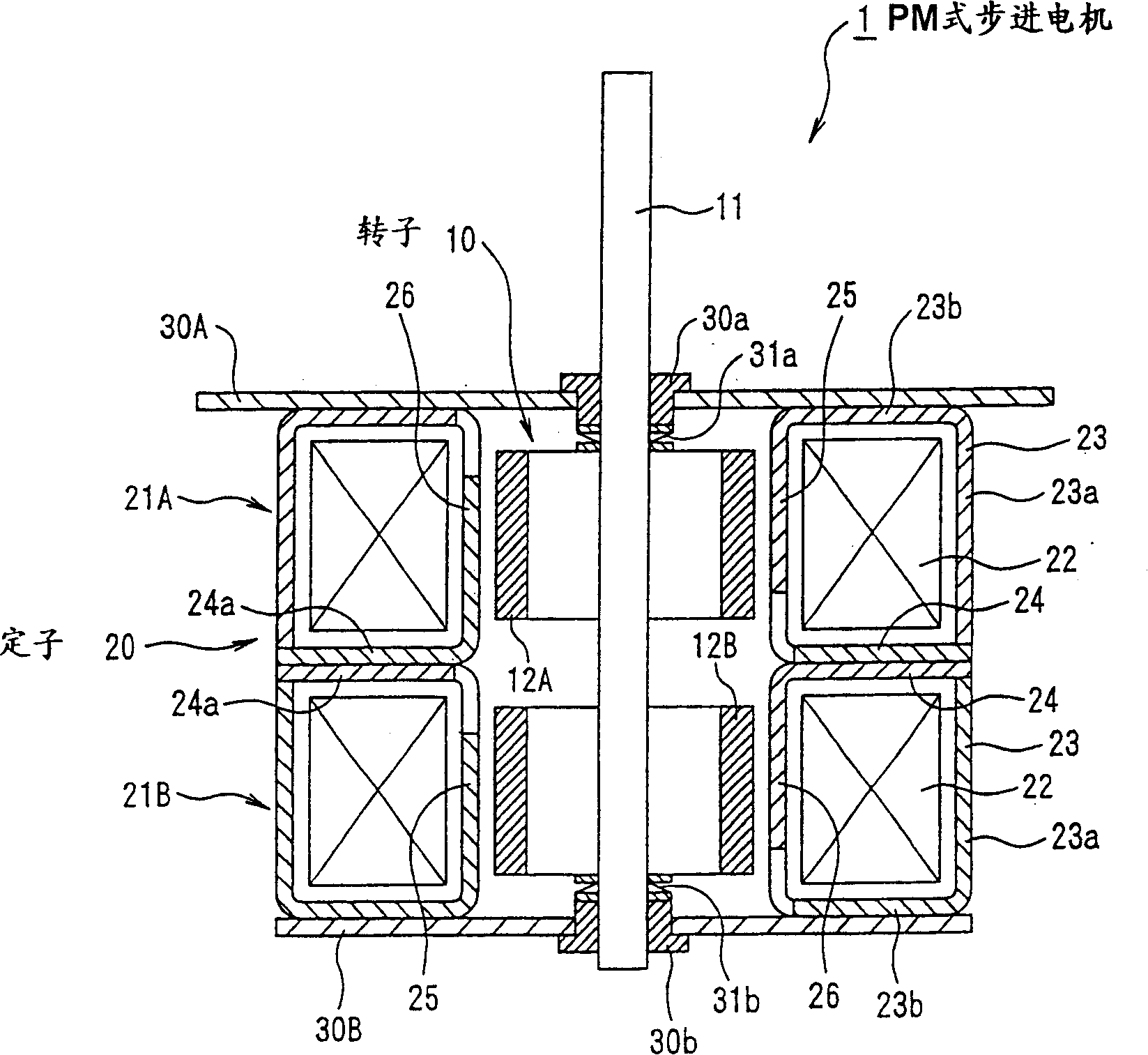
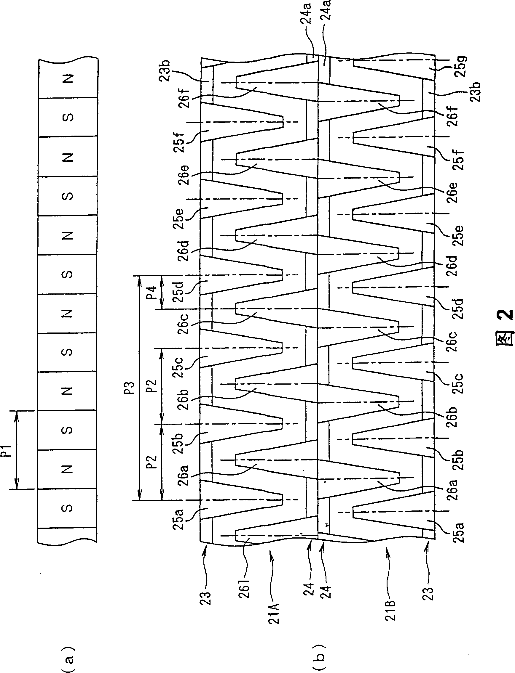
[0114] figure 1 and 2 represent a first embodiment of the invention. In this embodiment, the invention is applied to a two-phase permanent magnet stepper motor.

[0115] That is, the permanent magnet type stepping motor 1 of this embodiment is equipped with a rotatable rotor 10 and a stator 20 surrounding the rotor 10 in a non-contact state.

[0116] The rotor 10 has a rotary shaft 11 rotatably supported at two positions axially separated from each other by (intermediately) bearings 30a and 30b at two positions separated from each other by covers 30A and 30B as stator side members. However, between the rotating shaft 11 and the bearings 30a and 30b, there are provided leaf springs 31a and 31b which serve as elastic members capable of elastically deforming in the axial direction, and therefore, the rotating shaft 11 is relatively movable within a range. The covers 30A and 30B move axially, and in this range, the leaf springs 31a and 31b can be elastically deformed.

[0117] ...


PUM


Abstract

The present invention relates to a permanent magnetic step-by-step motor which can further reduce the higher harmoninc elements of detent torque. The n-set of the tooth group consisting of m stator pole teeth 25a to 25f, 26a to 26f are set respectively to the external yoke 23 and internal yoke 24, and the pitch P2 of stator pole teeth 25a to 25f, 26a to 26f, the pitch P3 of the tooth groups and the pitch P1 between N pole and S pole of the permanent magnet are set to establish the relationship P2 notequal P1, P3 notequal m*P1, P3 notequal m*P2, wherein P1, P2, P3 are electric angles, and m and n are integers equal to or larger than 2.

Description

technical field [0001] The invention relates to a PM type stepping motor, in particular to a PM type stepping motor capable of further reducing vibration and noise. Background technique [0002] A conventional permanent magnet type stepping motor proposed by the present applicant is disclosed in Japanese Unexamined Patent Application Publication No. 10-136631. In the conventional permanent magnet stepping motor, in order to effectively reduce the high-order harmonic component of the starting torque, the pole teeth of the yoke of the stator unit are arranged to deviate from positions at equal intervals. That is, when the pole teeth are (at) equal intervals away from the position (arranged so as to deviate from the position), substantially higher harmonic components of the starting torque appearing in the yoke can be canceled and reduced. [0003] Other conventional permanent magnet stepper motors are disclosed in Japanese Unexamined Patent Application Publication No. 5-25271...

Claims


Application Information

Patent Timeline
IPC IPC(8): H02K37/14H02K1/14
CPCH02K37/14H02K1/145
Inventor 小池良和池上昭彦
Owner SEIKO EPSON CORP
Why Eureka
Try Eureka