Cam valve

A cam and camshaft technology, applied in the direction of lift valve, valve details, valve device, etc., can solve the problems of complex process, increased use cost and high use cost, and achieve simple processing technology, improved sealing performance, and easy processing and manufacturing. Effect

Inactive Publication Date: 2008-07-02
常殿林
View PDF6 Cites 4 Cited by
  • Summary
  • Abstract
  • Description
  • Claims
  • Application Information

AI Technical Summary

Problems solved by technology

For this kind of common mechanical valve, the phenomenon of dripping and leaking is common, and it is difficult to completely solve it.
In addition, some valves are also equipped with threaded stems or screw rods. During the operation, the axial stroke of the stem shaft is relatively large, which brings difficulties to the sealing of the bonnet and also causes leakage of the bonnet.
Although this common valve has the above-mentioned shortcomings, it is still widely used as a control valve in various pipelines such as water, oil, and steam, and there is no suitable substitute product.
The applicant applied for a cam valve in 1997. The patent number is 97105006.6. Although the above-mentioned technical problems have been solved, due to the complex process and difficult processing, it needs three parts in one body to complete the processing, and the valve core cannot be replaced separately after damage. , so the cost of use is high. When the valve is required to work at a fixed flow rate, the position of the valve core cannot be fixed, so the flow rate of the fluid cannot be guaranteed
Moreover, the valve core is large in size and easy to rust, causing the valve to fail to work normally and increasing the cost of use

Method used


Image

  • Cam valve
  • Cam valve
  • Cam valve

Examples


Embodiment Construction

[0016] The present invention will be described in further detail below in conjunction with the accompanying drawings and specific embodiments.

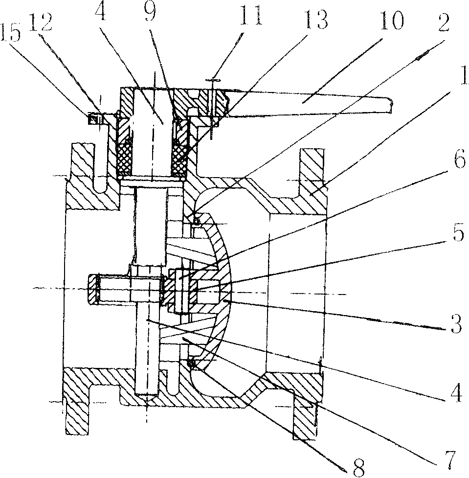
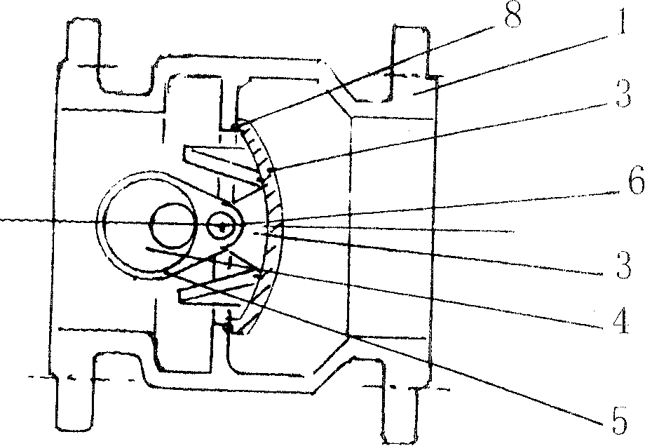
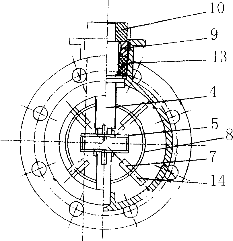
[0017] A cam valve, comprising a valve body 1, a valve seat 2, a valve disc 3, and a handle 10, the valve disc 3 is fixedly connected to one end of a coupling sleeve 5 through a connecting shaft 6, and the other end of the coupling sleeve 5 is connected to a camshaft 4, The camshaft 4 drives the valve disc 3 to move axially, and the camshaft 4 is fixedly connected with the handle 10 .

[0018] The valve flap 3 is provided with a slide block 7, and the valve seat 2 is provided with a support block 14 corresponding to the slide block 7, and the support block 14 is in the same body as the valve seat 2.

[0019] The slider 7 is in the same body as the disc 3, and there are 4 sliders 7, and the 4 sliders are arranged vertically and symmetrically. There are four supporting blocks 14, and the four supporting blocks are vertically symmetrica...


PUM


Abstract

The present invention relates to a valve, in particular, it relates to a cam valve. Said cam valve is characterized by adopting cam shaft and connecting sleeve and utilizing intermediate connecting shaft to drive valve Clark so as to implement control. Said cam valve includes valve body, valve seat, valve Clark and handle. Said valve clark is fixedly connected with one end of connecting sleeve by means of intermediate connecting shaft, another end of said connecting sleeve is connected with the cam shaft; said cam shaft can be used for driving valve clark and making it implement axial movement, and the cam shaft is fixedly connected with the handle.

Description

technical field [0001] The invention relates to a valve, in particular to a cam valve which is controlled by using a camshaft and a connecting sleeve to drive a valve clack through an intermediate shaft. Background technique [0002] During the operation of common mechanical valves such as ball valves, gate valves or globe valves, due to the frequent friction between the spherical surface in the valve body or the plane of the gate plate and the seat seal, the surface is easily scratched, thus damaging the sealing surface and making the sealing The pressure decreases and a drip occurs. For this common mechanical valve, drip phenomenon is ubiquitous, and is difficult to thoroughly solve. In addition, some valves are also equipped with threaded valve stems or screw rods. During the operation, the axial stroke of the valve stem shaft is relatively large, which brings difficulties to the sealing of the bonnet and also causes leakage of the bonnet. Although this common valve has...

Claims


Application Information

Patent Timeline
Patent Type & Authority Patents(China)
IPC IPC(8): F16K1/00F16K31/524
Inventor 常殿林
Owner 常殿林
Why Eureka
Try Eureka