
Motor and transmission construction for a hand-held tool

A technology of hand-held tools and transmission devices, which is applied in portable motorized devices, sawing machine devices, manufacturing tools, etc., and can solve problems such as large bending loads on motor shafts and large axial distances

Inactive Publication Date: 2008-07-09
ROBERT BOSCH GMBH
View PDF5 Cites 0 Cited by
  • Summary
  • Abstract
  • Description
  • Claims
  • Application Information

AI Technical Summary

Problems solved by technology

The disadvantage of this construction is that the axial distance of the ring gear from the bearing of the motor shaft is relatively large, so that the motor shaft will be exposed to relatively large bending loads

Method used


Image

  • Motor and transmission construction for a hand-held tool
  • Motor and transmission construction for a hand-held tool

Examples


Embodiment Construction

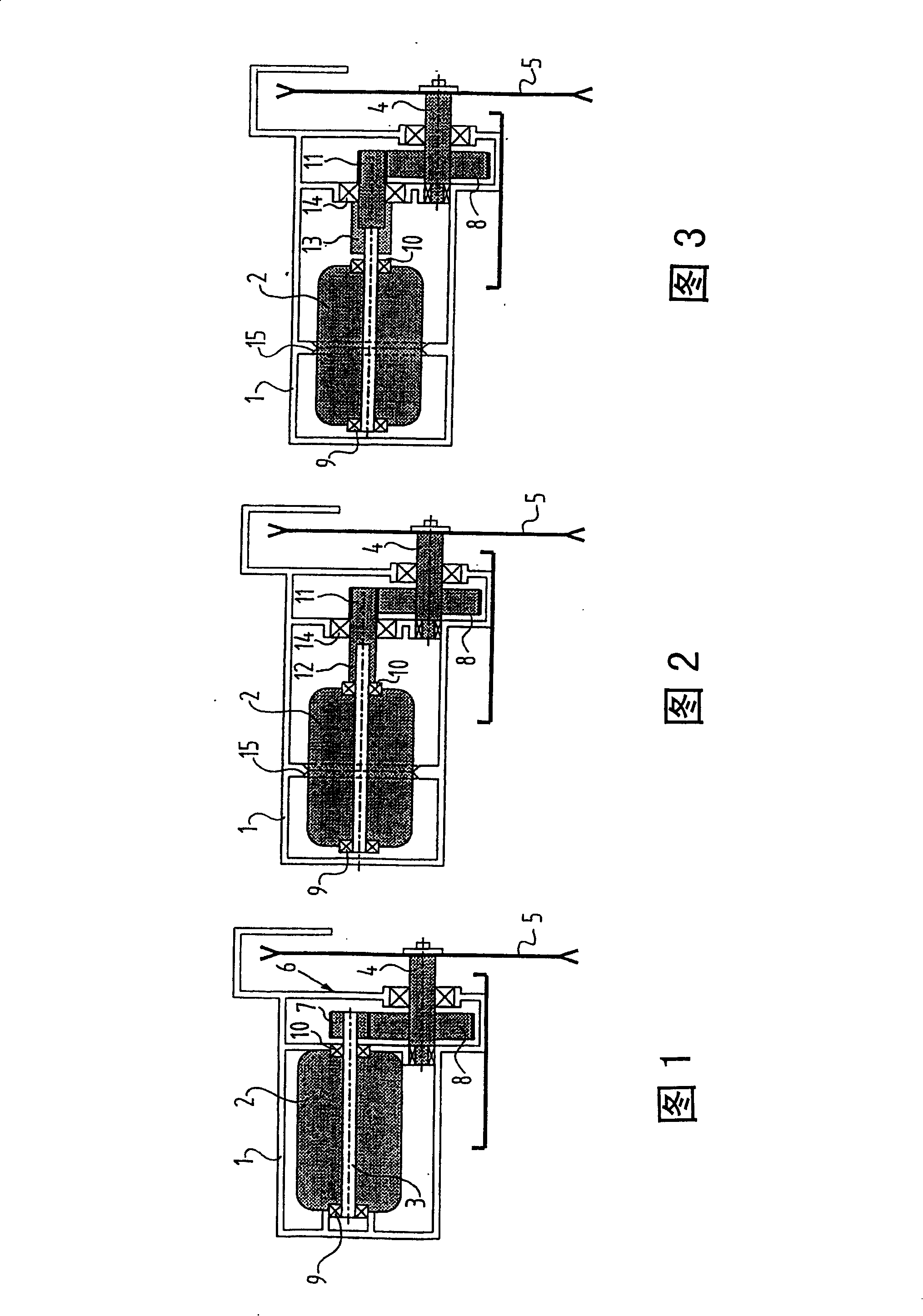
[0016] Figure 1 shows a known circular saw. The circular saw comprises a housing 1, a motor 2 in which a motor shaft 3 is mounted, and a tool shaft 4 rotatably mounted in the housing and on which a circular saw blade 5 is mounted. The tool shaft 4 can be driven by the motor shaft 3 via a transmission 6 . The transmission comprises at least two intermeshing gears 7 , 8 , wherein the first gear 7 is press-fitted on the outer end of the motor shaft 3 . The motor shaft is further fitted near its two outer ends in bearings 9 , 10 , so that the motor 2 with the motor shaft 3 is clamped in the housing via these bearings 9 , 10 .

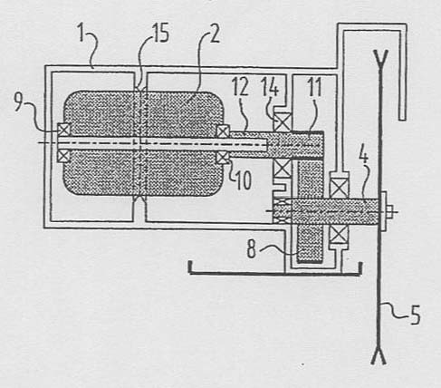
[0017] 2 and 3 show two embodiments of a circular saw according to the invention. The differences between these circular saws according to the invention and the known circular saw of FIG. 1 will be clarified below. Firstly, the first gear wheel according to the invention is formed by a shaft 11 with a ring gear on the outer surface of its first outer end...


PUM


Abstract

The invention relates to a hand-held tool, comprising a housing (1), a motor (2) arranged therein and having a motor shaft (3), and a tool shaft (4) which is received rotatably in the housing (1) and which is drivable by the motor shaft (3) via a transmission (6), wherein the transmission (6) comprises at least two mutually engaging toothed wheels (7,8), a first toothed wheel (7) of which is coupled to the motor shaft, wherein the first toothed wheel is situated, as seen in longitudinal direction of the motor shaft, in line with the outer end of the motor shaft, wherein the first toothed wheel is mounted in the housing (1).

Description

technical field [0001] The invention relates to a hand tool, in particular a battery-operated circular saw, comprising a housing, a motor arranged in the housing and having a motor shaft mounted in the motor housing, and a tool shaft, the tool shaft rotatably installed in the housing and driven by the motor shaft through a transmission, wherein the transmission includes at least two intermeshing gears, wherein a first gear is connected to the motor shaft, the axis of the first gear is in line with the The axes of the motor shaft are aligned. Background technique [0002] In typical hand tools, the motor is mounted within the housing. In addition, the motor shaft is mounted at both ends by means of bearings placed in the housing. The motor shaft protrudes at an outer end so that the first gear wheel of the transmission can be mounted thereon. The first gear drives a second gear. In the case of a single-stage transmission, a second gear is mounted on the tool shaft to driv...

Claims


Application Information

Patent Timeline
IPC IPC(8): B23D47/12B25F5/00B27B9/00
CPCB27B9/00B23D47/12B25F5/001
Inventor 彼得·万宁克霍夫
Owner ROBERT BOSCH GMBH
Learn More