
Eureka
For R&D, Eureka makes reading and utilizing patents & technical documents easy.
Eureka AIR
Designed for self-driven R&D workflows. Generate viable solutions, solve complex R&D challenges, empower your innovation with AI.

Eureka Materials
Designed for material experts only. Revolutionize your material R&D, from search, analyze, to developing new materials.

TechResearch
Generate reliable direction feasibility study reports for your R&D in just a few steps.

TechSeek
Discover and master advanced knowledge NOW. Basics, ideas, possibilities, all at once.

TechMind
As an expert in R&D Theories, TechMind can generates customized viable solutions instantly.

TechRisk
Analyze your overall solution with one click, know your potential R&D risks in advance.

TechMonitor
Get weekly tech updates, stay abreast of the latest tech innovations and key insights.
Steam pipeline laying method for thermoelectric plant
A technology for a steam pipeline and a laying method, which is applied in the direction of pipeline laying and maintenance, protection of pipelines and pipeline supports through thermal insulation, etc. Dislocation of pipes and steel shells, etc., to achieve the effect of strengthening thermal insulation, waterproofing and protection, simple structure and convenient construction
- Summary
- Abstract
- Description
- Claims
- Application Information
AI Technical Summary
Problems solved by technology
Method used
Image

Examples
Embodiment
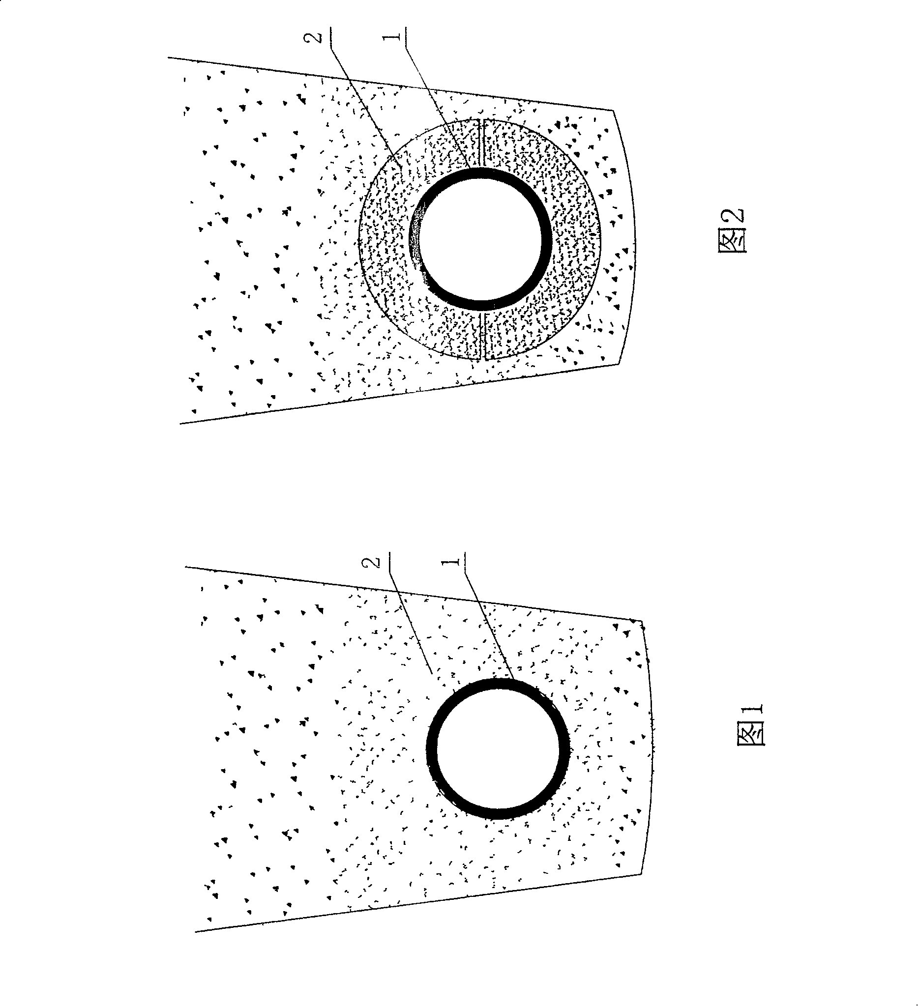
[0046] As shown in accompanying drawing 1, in thermal power plant steam pipeline laying method of the present invention, the laying of thermal insulation waterproof underground pipeline comprises the following steps:
[0047] a. After excavating the pipeline ditch, fill the bottom of the ditch with sand as the foundation, compact and level it;
[0048] b. Fill with 10-30cm thick fly ash, lay the steam pipe on the fly ash, and then cover the steam pipe with 10-30cm thick fly ash;
[0049] c. Fill the top of the fly ash with gravel soil.
[0050] Once the fly ash encounters water or moisture, it will solidify immediately around the steam pipe 1 to form a solid fly ash waterproof insulation pipe shell 2.
[0051] As shown in Figure 2, in the laying process of thermal insulation and waterproof underground pipelines, the fly ash can also be processed into a semicircular fly ash waterproof and thermal insulation shell 2 by using a mold, and then half of the waterproof and thermal ins...
PUM
 Abstract
Description
Claims
Application Information
 - R&D Engineer
- R&D Manager
- IP Professional
- Industry Leading Data Capabilities
- Powerful AI technology
- Patent DNA Extraction
Browse by: Latest US Patents, China's latest patents, Technical Efficacy Thesaurus, Application Domain, Technology Topic, Popular Technical Reports.
© 2024 PatSnap. All rights reserved.Legal|Privacy policy|Modern Slavery Act Transparency Statement|Sitemap|About US| Contact US: help@patsnap.com