Heat pump system of heat pump water heater

A heat pump water heater and heat pump system technology, which is applied to the improvement field of the heat pump system of the existing heat pump water heater, can solve the problems such as the reduction of the refrigerant circulation flow, the reduction of the heating capacity of the heat pump system, the increase of the exhaust pressure difference, and the improvement of the return flow. The effect of increasing the superheat of the air, improving the heating efficiency, and increasing the evaporation pressure

Inactive Publication Date: 2008-07-23
CHANGSHU TIANYIN NEW ENERGY
View PDF7 Cites 5 Cited by
  • Summary
  • Abstract
  • Description
  • Claims
  • Application Information

AI Technical Summary

Problems solved by technology

However, in practical application of this heat pump system, it is inevitable to encounter two problems: one is that as the ambient temperature decreases, the evaporation efficiency of the evaporator 4' decreases significantly, and the suction and exhaust pressure difference of the compressor 1' Increase, the density of the refrigerant sucked by the compressor 1' decreases, and the circulation flow of the refrigerant inside the heat pump system decreases, resulting in a decrease in the heat provided by the heat pump system to the water storage tank, especially in winter when the ambient temperature is lower than -5°C Sometimes, its thermal efficiency is very unsatisfactory, and sometimes even the thermal efficiency is lower than 1, causing the heating capacity to fail to meet the requirements, and the hot water is not hot, which greatly affects the promotion of heat pump water heaters in the market and affects the heat pump water heater. The competition between the water heater and other traditional water heaters; the second is that when the ambient temperature is lower than -5°C, frost is easy to form on the outer surface of the evaporator 4', and the existence of frost will affect the evaporation of the coolant in the evaporator 4' Therefore, it is necessary to defrost the evaporator 4' regularly, and the shorter the defrosting cycle, the lower the heating efficiency of the entire heat pump system

Method used


Image

  • Heat pump system of heat pump water heater
  • Heat pump system of heat pump water heater

Examples


Embodiment Construction

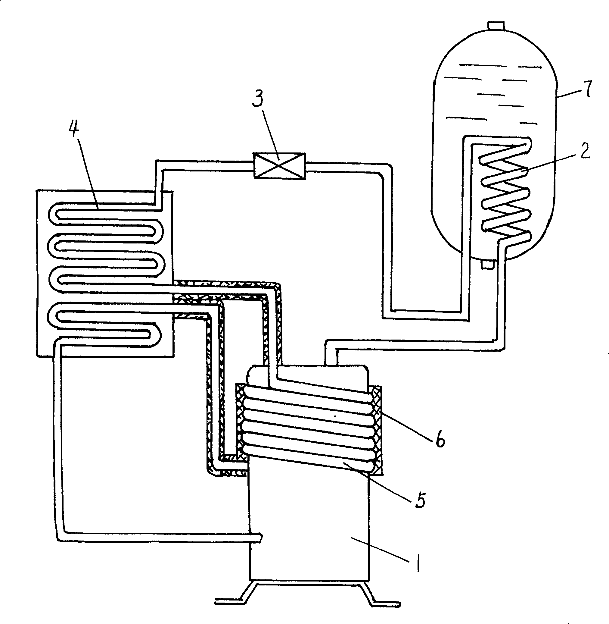
[0012] Please refer to figure 1 The heat pump system of the heat pump water heater of the present invention is mainly composed of a compressor 1, a condenser 2, a throttling element 3, and an evaporator 4 connected in sequence through conduits, and a coil 5 is coiled outside the shell of the compressor 1 , the coil 5 is a copper coil, and a pair of leading ends thereof are respectively connected in series with the circuit of the evaporator 4 . The outer surface of the coil pipe 5 is wrapped with a thermal insulation layer 6, and the thermal insulation layer 6 plays the role of thermal insulation. The throttling element 3 can be any one of a capillary tube, an electronic expansion valve, a thermal expansion valve, and a throttle valve.

[0013] Please see below figure 1 To describe the working process of the heat pump system of the present invention: the high-temperature and high-pressure gas from the compressor 1 is introduced into the condenser 2 through the copper pipe, ...


PUM


Abstract

The heat pump system is composed of compressor, condenser, throttling element, and evaporator connected in sequence through pipes. Coil pipe is wound on compressor, and two ends of coil pipe are connected to loop of evaporator. Advantages are: recovering quantity of heat released to environment by compressor before the invention; recovered quantity of heat is provided to evaporator to raise vapor pressure and to improve superheat degree of return-air of compressor in condition of low temperature. Test shows that in -5 deg.C of ambient temperature, thermal efficiency is raised 30%, and heating capacity is raised 35%. Since coil pipe is connected to loop of evaporator, thus, temperature of evaporator is higher than ambient temperature. The ambient temperature can be lowered than-5 deg.C when evaporator runs without frost. Or frost occurs defrosting cycle can be prolonged so as to raise efficiency of producing heat.

Description

technical field [0001] The invention relates to a heat pump system of a heat pump water heater, which is an improvement to the heat pump system of the existing heat pump water heater. Background technique [0002] The heat pump system of the existing heat pump water heater or the loop of the heating system such as figure 2 As shown, the heat pump system is mainly composed of a compressor 1', a condenser 2' (that is, a metal condensing coil), a throttling element 3', and an evaporator 4' connected in sequence through conduits. Its working mechanism is: refrigeration The agent comes out of the compressor 1' to form a high-temperature and high-pressure gas, which is introduced into the condenser 2' placed in the water storage tank of the water heater through the conduit, and after the condenser 2' exchanges heat with the water in the water storage tank of the water heater, it becomes a low-temperature and high-pressure liquid. Then it is introduced into throttling element 3' t...

Claims


Application Information

Patent Timeline
Patent Type & Authority Patents(China)
IPC IPC(8): F25B1/00F25B30/02
CPCF25B2400/05
Inventor 朱雪忠倪学中钱军钱虎
Owner CHANGSHU TIANYIN NEW ENERGY
Why Eureka
Try Eureka