
The rotating type electric sign board and method for driving thereof

An electronic display and rotary technology, applied in display devices, circuits, electrical components, etc., can solve problems such as the increase in the size of the electronic display panel, the inability of the drive motor to correctly display the required text or image data, and the increase in cost.

Inactive Publication Date: 2008-07-30
MY MEDIA
View PDF7 Cites 0 Cited by
  • Summary
  • Abstract
  • Description
  • Claims
  • Application Information

AI Technical Summary

Problems solved by technology

[0011] However, the aforementioned conventional rotary electronic display panel has the disadvantage that required text or image data cannot be correctly displayed due to the non-constant rotational speed of the driving motor, so a driving motor controller is required to maintain a constant rotational speed of the driving motor, thereby resulting in increased cost and increased size of the electronic display board
Also, another rotary electronic display panel using an encoder including a disc and a photocoupler is very expensive, thereby inevitably increasing the manufacturing cost and reducing the price competitiveness of the product in the market

Method used


Image

  • The rotating type electric sign board and method for driving thereof
  • The rotating type electric sign board and method for driving thereof
  • The rotating type electric sign board and method for driving thereof

Examples


Embodiment Construction

[0036] Preferred embodiments of the present invention will now be described in detail with reference to the accompanying drawings. In the drawings, the same or similar elements shown in different drawings are denoted by the same reference numerals. In the following description, descriptions of well-known functions and constructions incorporated herein will be omitted when it may obscure the essence of the present invention.

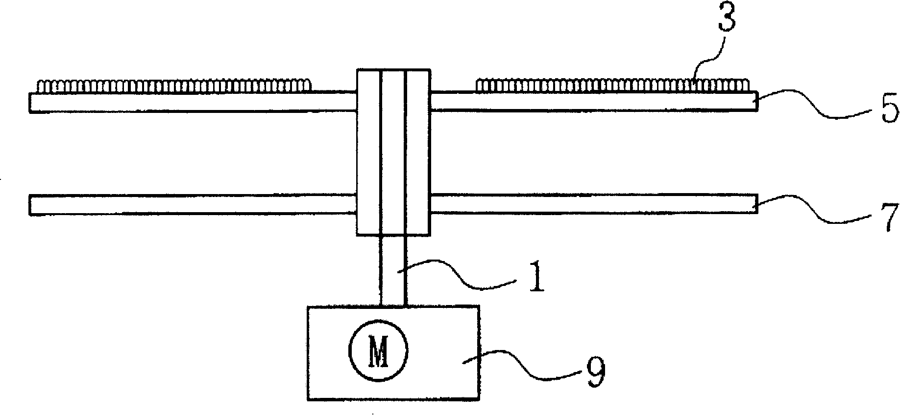
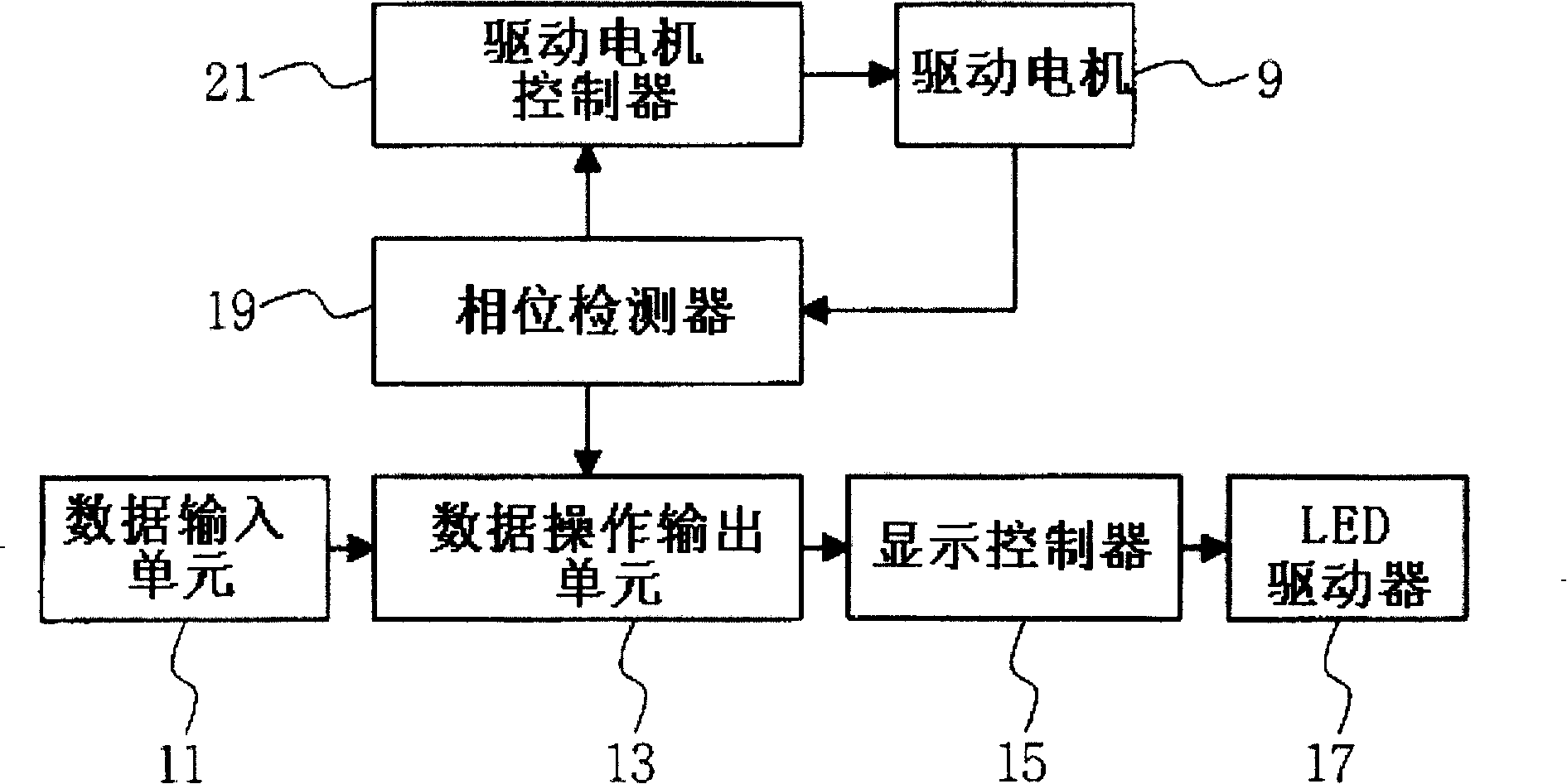
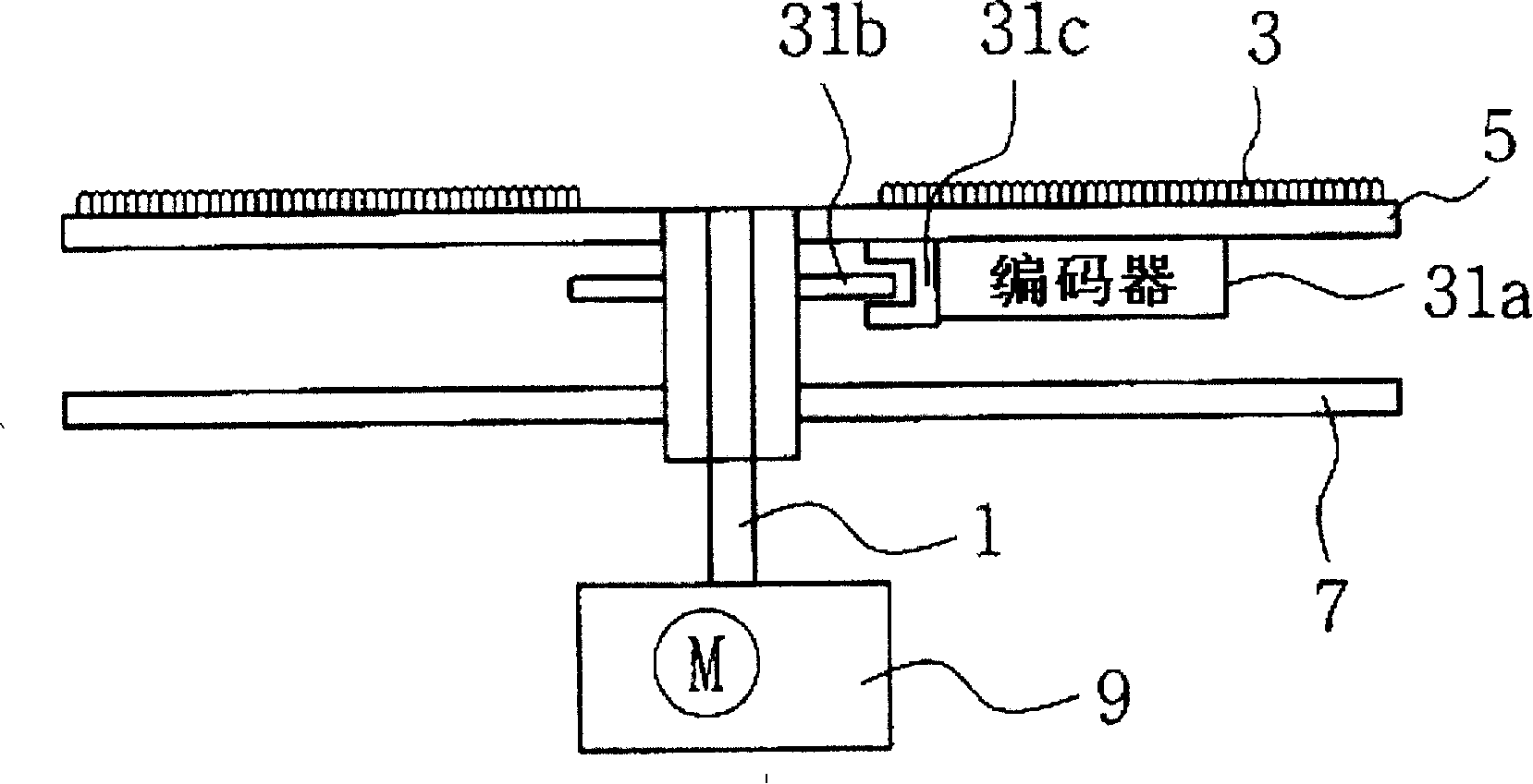
[0037] According to the rotating electronic display panel of the present invention, the origin pulse is generated when the rotating body rotates around a reference point, so that the LED arrays arranged on the rotating body are selectively turned on or off when the rotating body rotates with a predetermined radius of rotation, thereby Text or image data can be displayed at predetermined positions. The rotary electronic display panel divides the period of the origin pulse by the number of effective lines separated along the radius of rotation to generate ...


PUM


Abstract

A rotary electronic display board and a method for driving the same. The rotary electronic display board switches individual LEDs on or off at their correct positions irrespective of a variation in rotation speed of a drive motor, and correctly and sharply indicates text and image data without using a high-priced encoder, such that it can reduce its own production cost and increase the price competitiveness of a product. The rotary electronic display board includes: a drive motor for rotating a rotary shaft at a predetermined speed; a revolution solid connected to the rotary shaft, which rotates with a predetermined turning radius; an LED array arranged on the revolution solid; an origin pulse generator for generating an origin pulse whenever the revolution solid rotates once; a line pulse generator for calculating a rotation period of the revolution solid using the origin pulse, and generating a plurality of line pulses each having a period corresponding to a division result value which is acquired by dividing the rotation period of the revolution solid by the number of virtual areas separated along the turning radius of the revolution solid; and a controller for generating a control signal to selectively switch on or off the LED array so that desired text and image data is displayed at each line pulse generation time.

Description

technical field [0001] The present invention relates to an electronic display board (also known as an electronic signage board), and more particularly to a method for displaying text and image data more clearly and significantly reducing product manufacturing costs by selectively turning on or off LED (Light Emitting Diode) arrays. A rotary electronic display panel and a method for driving the electronic display panel. Background technique [0002] Generally, electronic display boards are used to display images or text information. Recently, various electronic display panels composed of optical fibers, LEDs, LCDs, etc. have been proposed. In particular, due to the wide application of large-scale high-brightness and multi-color LEDs, various electronic display boards have been commercially developed, such as large-size electronic display boards, subway-guided electronic display boards, and other electronic display boards for advertising. display board and more. [0003] Ho...

Claims


Application Information

Patent Timeline
Patent Type & Authority Patents(China)
IPC IPC(8): G09F11/23G09F9/33G09F9/37G09F13/00G09F13/32G09F19/12G09G3/02G09G3/20H01L33/00
CPCG09G3/005G09G3/2011G09G2310/02G09F9/33G09F11/23
Inventor 柳承铉
Owner MY MEDIA
Features
  • Generate Ideas
  • Intellectual Property
  • Life Sciences
  • Materials
  • Tech Scout
  • Unparalleled Data Quality
  • Higher Quality Content
  • 60% Fewer Hallucinations
Learn More