
Francis turbine

A technology of impellers and tires, applied in mechanical equipment, engine components, machines/engines, etc., can solve problems such as wear and tear enhancement, changes in service conditions, and reduced hydraulic mechanical efficiency

Inactive Publication Date: 2008-08-06
GE RENEWABLE TECH
View PDF7 Cites 0 Cited by
  • Summary
  • Abstract
  • Description
  • Claims
  • Application Information

AI Technical Summary

Problems solved by technology

[0006] [06] However, especially in the case of refurbishment of existing units, the operating conditions of the turbine may have changed, specifically: it may have been retrofitted by reducing the speed and / or increasing the pressure head, in which case the blow The orientation of the flow edge is no longer adapted to the angle of incidence of the incoming water flow
In this case, eddy currents and / or cavitation will be generated near the lower and / or upper surface of the blade, which will reduce the efficiency of the hydraulic machinery and have an enhanced effect on wear and tear phenomena

Method used

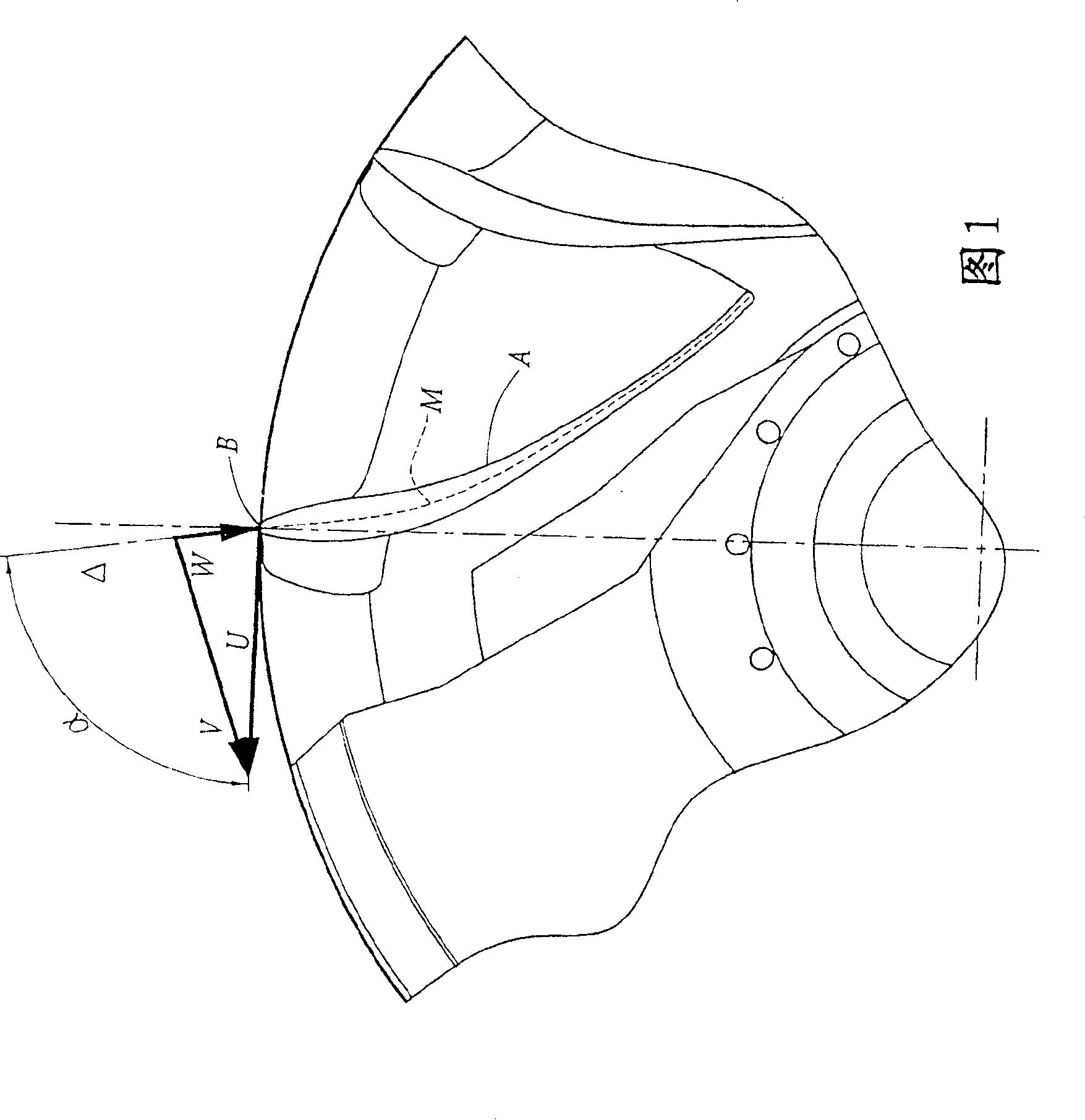

Image

  • Francis turbine
  • Francis turbine
  • Francis turbine

Examples


Embodiment Construction

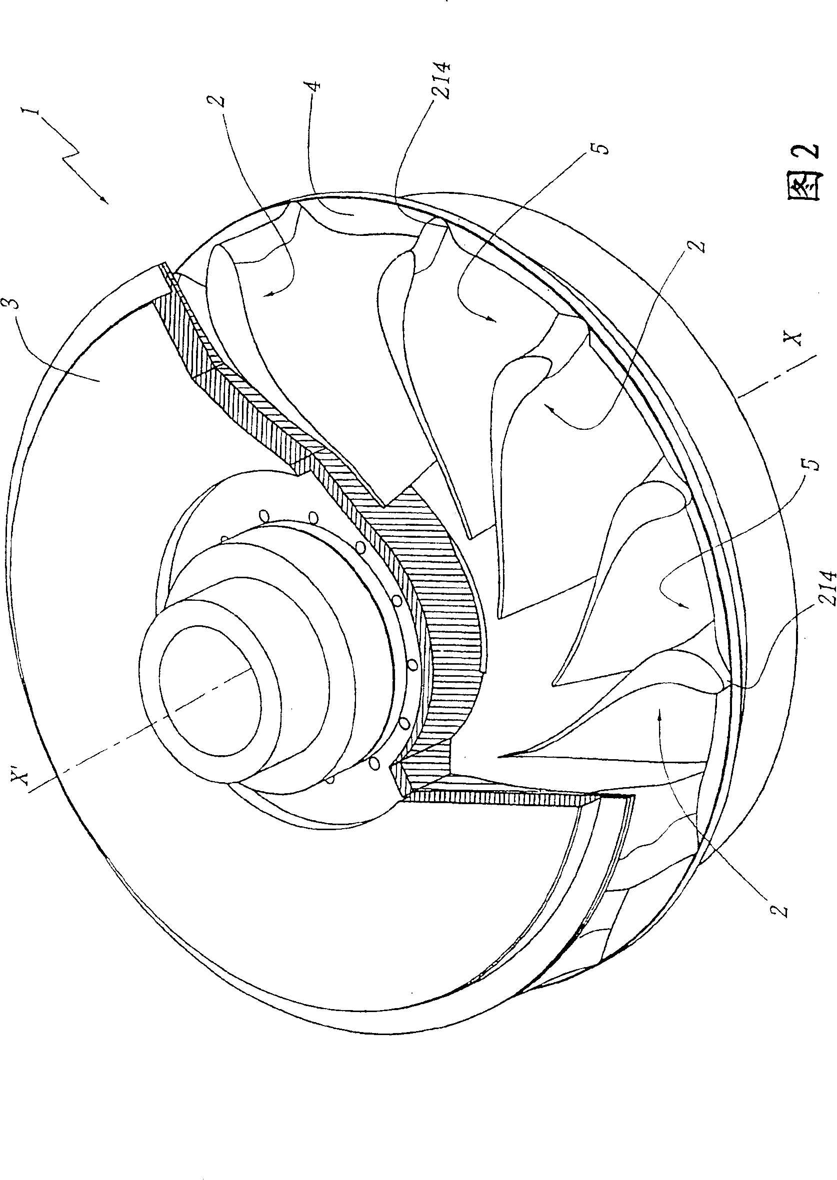
[0020] [20] Fig. 2 to Figure 4 The impeller 1 shown comprises a number of identical blades 2 distributed around the central axis of rotation XX' of the impeller 1 . A top plate 3 is provided on the upper part of the impeller 1 , while a tire 4 serves as the lower boundary of the radially outer portion of the blade 2 . Thus, a flow channel 5 is formed between each pair of adjacent blades 2 , this channel being delimited by the top plate 3 and the rim 4 .

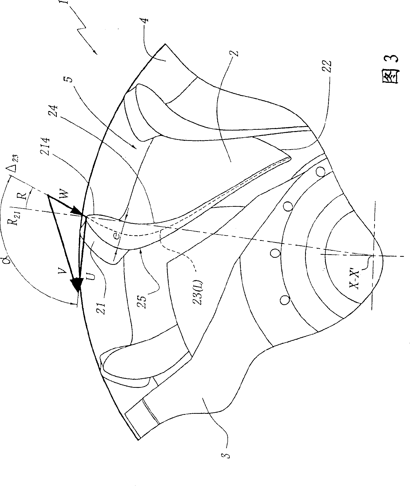
[0021] [21] Reference numeral 21 refers to the flow edge of the blade 2 . 22 designates the overflow edge of the blade. The bisector 23 of the blade 2 is defined as: the curve at the same distance from the lower surface 24 and the upper surface 25 of the blade 2 on each cross-section of the blade.

[0022] [22] L refers to the average length of the bisector 23, which is considered to be equal to half the sum of the two length values ​​of the bisector, one of which is the length of the blade 2 on the plane of the top plate ...


PUM


Abstract

The invention relates to a Francis turbine and a hydraulic turbine comprising one such Francis turbine. The inventive Francis turbine comprises a ceiling, a belt and blades ( 2 ) which extend between the ceiling and the belt and which define liquid flow channels therebetween. The ratio (e / L) of the maximum thickness (e) of each blade ( 2 ) to the average developed length (L) of the average fibre ( 23 ) thereof is between 0.1 and 0.2. According to the invention, over essentially the entire height of the leading edge ( 21 ), said average fibre ( 23 ) is oriented along a straight line (Delta23) which forms an angle (alpha) greater than 90 DEG in relation to the linear feed speed (U) of the leading edge ( 21 ) of the blade ( 2 ).

Description

technical field [0001] [01] The present invention relates to a Francis type impeller and a turbine equipped with the impeller. Background technique [0002] [02] Francis type impellers can be equipped in different types of hydraulic machinery, such as turbines, pumps, or pump turbines. A Francis-type impeller consists of blades arranged around a central axis of rotation forming passages between the blades to allow the passage of water. In the case of turbines, the geometry of these impeller blades is defined such that the water flow can generate a moment on the impeller. The power output of a turbine equipped with such an impeller depends on its geometry, in particular the diameter of the impeller, and on the rotational speed of the impeller. [0003] [03] In certain configurations of Francis-type hydraulic machinery, the diameter of the impeller is prescribed - especially in the case of repairs to existing In this case, the diameter of the impeller cannot be changed. ...

Claims


Application Information

Patent Timeline
Patent Type & Authority Patents(China)
IPC IPC(8): F03B3/12
CPCY02E10/223F05B2240/301F03B3/125Y02E10/20
Inventor D·巴赞M·H·库斯东
Owner GE RENEWABLE TECH
Learn More