Brushless dc electric machine and special stater iron core thereof

A brushed DC motor and stator iron core technology is applied in the manufacture of stator/rotor body, magnetic circuit shape/style/structure, magnetic circuit static parts, etc., which can solve the problem of prolonged starting time, increased motor torque, and starting torque. Large and other problems, to achieve the effect of large starting torque, suppression of axial vibration, and short starting time

Inactive Publication Date: 2008-08-06
横店集团东磁有限公司
View PDF8 Cites 0 Cited by
  • Summary
  • Abstract
  • Description
  • Claims
  • Application Information

AI Technical Summary

Problems solved by technology

[0005] The purpose of the present invention is to provide a brushless DC motor with a large starting torque, a shorter starting time of the motor and a shorter time for the motor rotor to achieve high-speed equilibrium and uniform rotation, and a special stator core thereof, which solves the problems caused by the motor rotor part of the existing motor. The addition of moving components will increase the torque of the motor when it starts, and at the same time, the start-up time and the time for the motor rotor to reach high-speed equilibrium and uniform rotation will also be prolonged, etc.

Method used


Image

  • Brushless dc electric machine and special stater iron core thereof
  • Brushless dc electric machine and special stater iron core thereof
  • Brushless dc electric machine and special stater iron core thereof

Examples


Embodiment 1

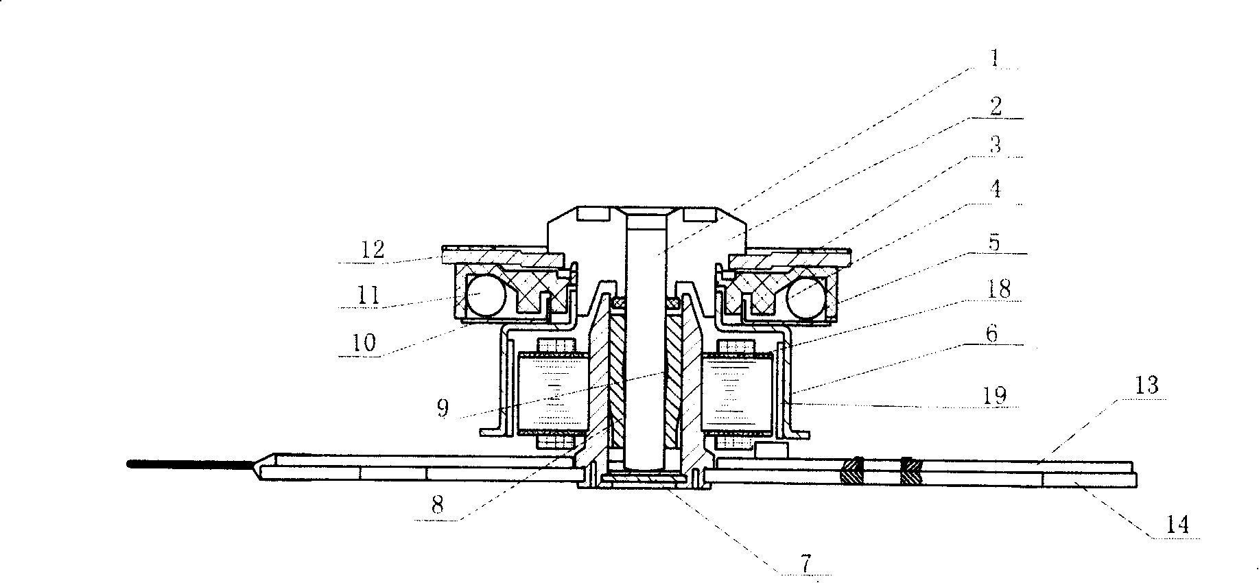
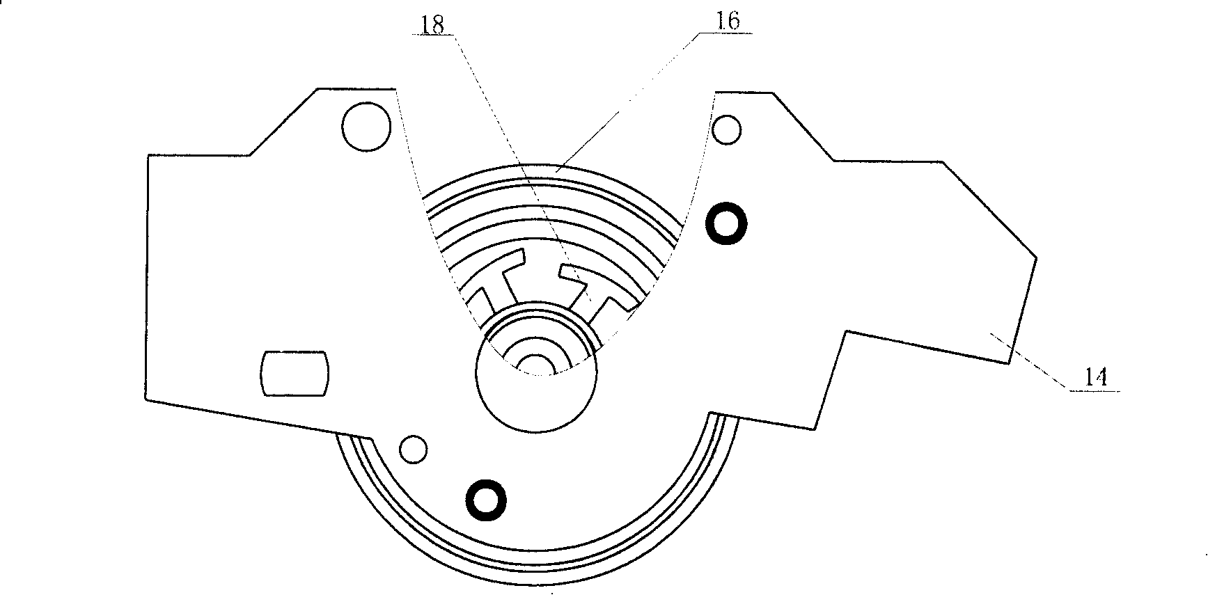
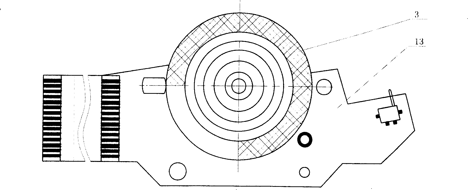
[0021] Embodiment 1: as figure 1 , figure 2 , image 3 , Figure 4 and Figure 5 As shown, the motor includes a stator core 18, a rotating shaft 1, a rotor cover 6 and a rotor 19 arranged on the inner wall of the rotor cover. The rotating shaft 1 passes through a through hole 182 in the center of the stator core and is rotatably supported in the stator core. The rotor The cover 6 rotates together with the rotating shaft, and the upper end of the rotating shaft is provided with a disc core 2 and a tray 5 which rotate synchronously with it. A spring is arranged between the pressure plates. The bottom of the rotor cover 6 is provided with a PCB board 13 and a PCB bottom plate 14, such as Figure 4 As shown, the PCB bottom plate is provided with an upwardly convex hollow convex body 16, the PCB board is provided with a through hole 15 for the hollow convex body 16 to pass through, and the end of the hollow convex body passing through the through hole 15 of the PCB board is p...

Embodiment 2

[0024] Embodiment 2: There are 4 poles evenly distributed on the circumference of the stator core, the distance R from the point on the outer contour of each pole to the center of the iron core gradually decreases in the same direction, and the points on the outer contour of the pole 181 of the stator core 18 The maximum and minimum distances R0:R1 to the core center are 1.01. Others are with embodiment 1.

Embodiment 3

[0025]Embodiment 3: There are 10 poles 181 evenly distributed on the circumference of the stator core, the distance R from a point on the outer contour of each pole to the center of the iron core gradually decreases in the same direction, and the distance R on the outer contour of the pole 181 of the stator core 18 The maximum distance and the minimum distance R0:R1 from the point to the core center are 1.05. Others are with embodiment 1.


PUM


Abstract

The invention relates to the principal axis motor used to rotate the data noting disc. The iron core frame related by the invention: the center of the stator iron core has the open hole, the several poles are distributed evenly on the circle of the iron core of the stator, the distance R between the point of the outer contour of every pole and the center of the iron core reduces gradually at the same direction, the percentage between the most distance R0 between the point of the pole outer contour of the iron core of the stator and the least distance R1 is 1.01-1.1, the said poles are 4-10, the outer contour of the pole of the iron core of the stator is arc or the beeline or the other curve figure. The startup moment is great, the driving time of the motor and the time consumed by the motor rotor to reach the high speed balance rotate are shorter.

Description

technical field [0001] The present invention relates to a brushless DC motor, and more particularly to a spindle motor for rotating a data recording disc (hereinafter referred to as "optical disc") such as CD, DVD, CD-ROM, DVD-ROM. technical background [0002] In an optical disc player, the rotary motor needs to rotate the optical disc at a high speed without vibration and eccentric movement of the optical disc and the turntable. In order for the rotating motor to rotate without vibration and eccentric motion, it is important to stably load the turntable in the disc during the high-speed rotation of the disc to keep the balance of the disc and to obtain the durability of the rotating motor. [0003] Therefore, someone has proposed a rotating motor called a CD player (application number: 03122307.9), which includes: a motor with a rotating shaft, a turntable that rotates with the rotating shaft and has an annular track groove, and is grooved along the track on the track groo...

Claims


Application Information

Patent Timeline
Patent Type & Authority Patents(China)
IPC IPC(8): H02K1/12H02K15/02
Inventor 何时金厉力波魏云冰吴锦星任秉知
Owner 横店集团东磁有限公司
Why Eureka
Try Eureka