Concave annular piezoelectric resonance gyroscope and production method thereof

A technology of piezoelectric resonance and manufacturing method, which is applied to gyroscope/steering sensing equipment, gyro effect for speed measurement, instruments, etc., and can solve the problem of large frequency splitting of gyro drive mode and detection mode, solid wave gyro cup shape Due to the large volume of the resonator body and the unstable fixing method of the gyro, the effects of large stiffness, short start-up time and favorable realization are achieved.

Active Publication Date: 2014-12-10
SHANGHAI JIAO TONG UNIV
View PDF9 Cites 4 Cited by
  • Summary
  • Abstract
  • Description
  • Claims
  • Application Information

AI Technical Summary

Problems solved by technology

[0006] This technology has the following disadvantages: the volume of the solid wave gyro cup-shaped resonator is too large, which limits its application in many conditions where the volume must be small; the piezoelectric electrodes of the cup-shaped vibrator chassis are bonded to the cup-shaped vibrator. There is a possibility of falling off under high-frequency vibration, and the reliability is not high; the processing technology of the gyroscope is relatively complicated, the processing cost is high, and it is not suitable for mass production; Large, the quality factor is difficult to improve; the gyro fixing method is unstable, and it is difficult to adapt to occasions that require high reliability

Method used


Image

  • Concave annular piezoelectric resonance gyroscope and production method thereof
  • Concave annular piezoelectric resonance gyroscope and production method thereof
  • Concave annular piezoelectric resonance gyroscope and production method thereof

Examples


Embodiment Construction

[0047] The present invention will be described in detail below in conjunction with specific embodiments. The following examples will help those skilled in the art to further understand the present invention, but do not limit the present invention in any form. It should be noted that those skilled in the art can make several modifications and improvements without departing from the concept of the present invention. These all belong to the protection scope of the present invention.

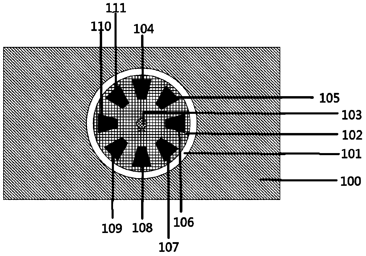
[0048] like figure 1 As shown, the present embodiment provides a concave annular piezoelectric resonant gyroscope, comprising:

[0049] a square base 100 with an upper surface;

[0050] an empty annular cavity 101 around a central location on the substrate 100;

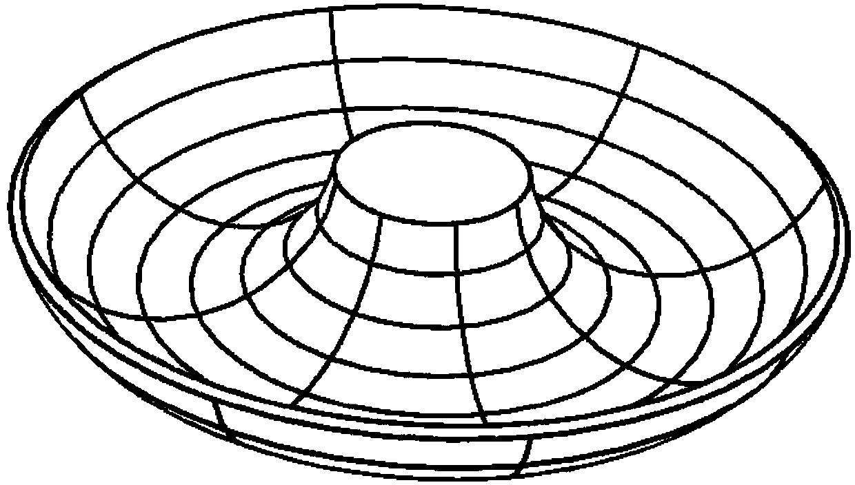
[0051] a concave annular piezoelectric resonator 102 on the substrate 100;

[0052] The support column 103 and the electrodes on the support column 103 are fixed on the base 100 to support the concave annular piezoelectric resonator 10...


PUM


Abstract

The invention provides a concave annular piezoelectric resonance gyroscope and a production method of the concave annular piezoelectric resonance gyroscope. The concave annular piezoelectric resonance gyroscope comprises a substrate, a hollow annular cavity which is arranged on the periphery of a central position of the substrate, a concave annular piezoelectric resonator which is arranged on the substrate, a supporting column which is fixed on the substrate and used for supporting the concave annular resonator, an electrode on the supporting column and eight electrodes which are symmetrically distributed on the outer surface of the concave annular resonator, wherein the concave annular piezoelectric resonator is located to be separated from the upper surface of the substrate so as to allow the vibration of the piezoelectric resonance gyroscope. The resonator is supported by the supporting column which is formed on the upper surface of the substrate, so that the stability is good, the influence of the supporting damping can be reduced, and the value Q and sensitivity of the gyroscope can be improved; the process is relatively simple and easy to realize; besides the central supporting, the resonator is separated from the substrate, so that the vibration is facilitated; by adopting the piezoelectric material, the overload resistance and impact resistance are high, the working resonance frequency is high, and the starting time is short.

Description

technical field [0001] The invention relates to a micro-electro-mechanical inertial sensor gyroscope in the technical field of micro-electro-mechanical (MEMS) systems, in particular to a concave annular piezoelectric resonance gyroscope and a manufacturing method thereof. Background technique [0002] As a carrier angular velocity sensitive inertial sensor, gyroscope plays a very important role in attitude control, navigation and positioning in traditional industrial fields such as aviation, aerospace, and shipbuilding. MEMS micro-gyroscopes have the advantages of small size and mass, low power consumption, low cost, good environmental adaptability, and high integration. [0003] With the development of my country's economy, the demand for MEMS micro-gyroscopes with high performance, small size and high reliability in the fields of military, industry and consumer electronics is becoming increasingly urgent. [0004] The piezoelectric gyroscope uses piezoelectric materials a...

Claims


Application Information

Patent Timeline
Patent Type & Authority Applications(China)
IPC IPC(8): G01C19/56G01C19/5691
CPCG01C19/56G01C19/5691G01C25/00
Inventor 张卫平孙殿竣唐健汪濙海刘亚东成宇翔邢亚亮陈文元
Owner SHANGHAI JIAO TONG UNIV
Why Eureka
Try Eureka