Supercharge Your Innovation With Domain-Expert AI Agents!

Evacuated shuttering member

A cavity mold and component technology, which is applied to building components, building structures, floor slabs, etc., can solve the problems of poor overall strength and rigidity, increasing the amount of steel and concrete, and damage to cavity formwork components, etc.

Inactive Publication Date: 2008-08-27
湖南邱则有专利战略策划有限公司
View PDF9 Cites 0 Cited by
  • Summary
  • Abstract
  • Description
  • Claims
  • Application Information

AI Technical Summary

Problems solved by technology

However, after being applied to the hollow floor, the cast-in-place concrete ribs formed between the cavity formwork members are all rectangular cast-in-place concrete ribs, and their mechanical performance is not very reasonable, so it is often necessary to increase the cross-sectional size of the cast-in-place concrete ribs , increase the amount of steel bars and concrete, and increase the cost of the floor. At the same time, there is no reinforcement structure in the cavity formwork member, so the overall strength and rigidity of the cavity formwork member are poor, and the cavity formwork member is prone to damage. Phenomenon, after being applied to the cast-in-place concrete hollow floor, it cannot participate in the force and transmission of the hollow floor

Method used


Image

  • Evacuated shuttering member
  • Evacuated shuttering member
  • Evacuated shuttering member

Examples


Embodiment Construction

[0058] The present invention will be further described below in conjunction with the accompanying drawings and embodiments.

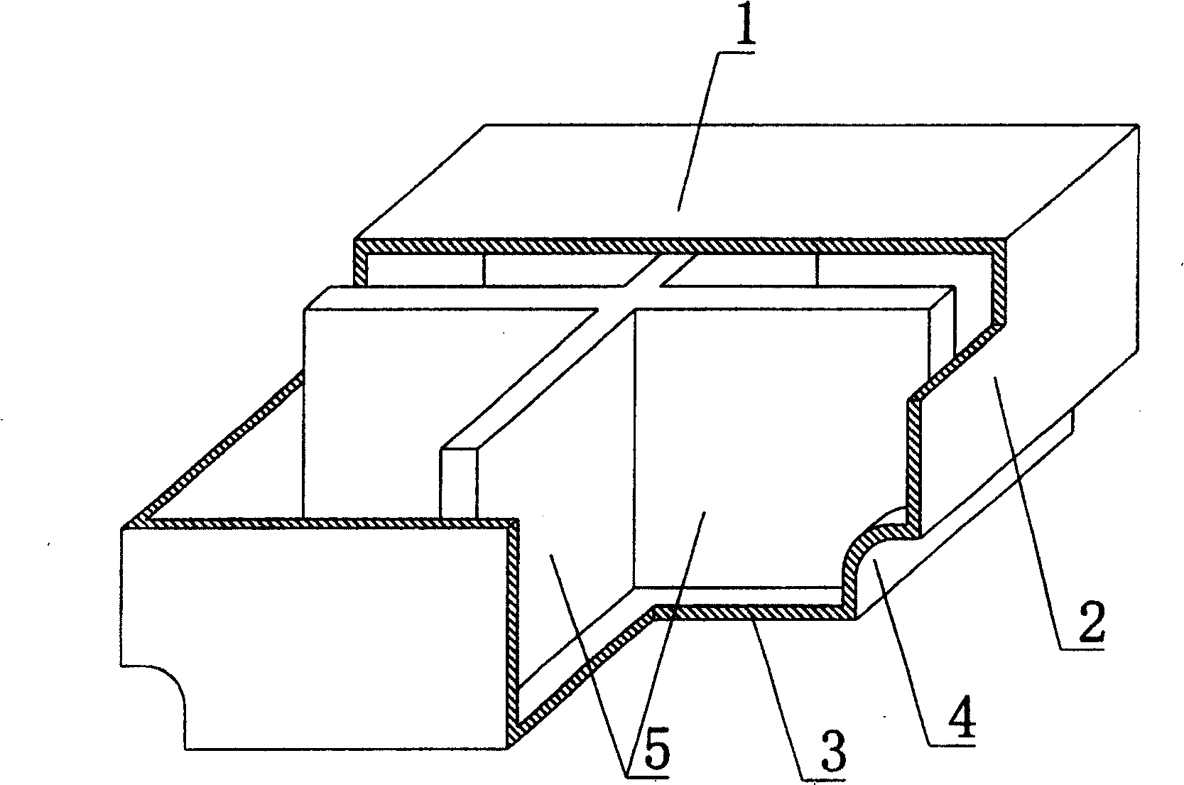
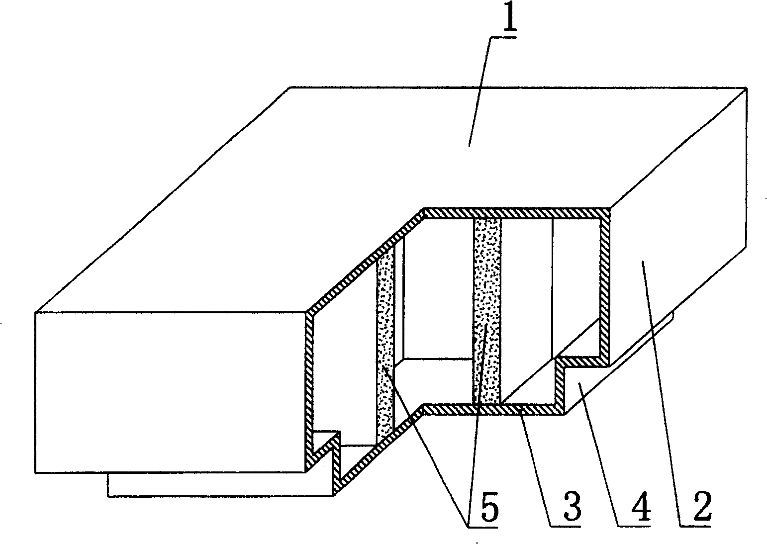
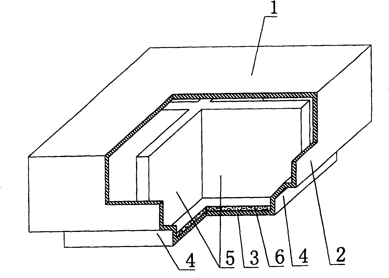
[0059] As shown in the accompanying drawings, the present invention includes an upper plate 1, surrounding side walls 2, and lower bottom 3, and the upper plate 1, surrounding side walls 2, and lower bottom 3 form a polyhedral cavity formwork member, which is characterized in that the cavity formwork At least one transverse corner of the lower part of the component is a female corner 4, and at least one piece of stiffening rib 5 is arranged in the cavity formwork member, and the upper plate 1 or the surrounding side wall 2 or the lower bottom 3 or the female part of the cavity formwork member A lamination layer 6 is laminated in at least one of the corners 4 . figure 1 It is a structural schematic diagram of Embodiment 1 of the present invention. In the accompanying drawings, 1 is the upper plate, 2 is the surrounding side wall, 3 is the lower bottom, ...


PUM


Abstract

The present invention provides an evacuated shuttering member including upper plate (1), a peripheral lateral wall (2), a bottom (3), the upper plate (1), the peripheral lateral wall (2), the bottom (3) compose the polyhedron evacuated shuttering member, which is characterized in that at least a lateral direction angle on bottom of the evacuated shuttering member is a hidden angle (4), a least a enforcing rib plate (5) is arranged in the evacuated shuttering member. Thus after the evacuated shuttering member is used for cast-in-situ building cover, the cast-in-situ bar between the evacuated shuttering member is inverse T shape, thus the mechanics capacity of the building is greatly improved, meantime, a enforcing rib plate is arranged in the evacuated shuttering member, such that the rigidity and intensity of the evacuated shuttering member are improved to avoid the dilapidation of the evacuated shuttering member, which is suitable for cast-in-situ concrete or pretension steel bar concrete building, building cover, wall body, base bottom plate and open web bridge.

Description

(1) Technical field [0001] The present invention relates to a cavity formwork member. (2) Background technology [0002] At present, the cast-in-place concrete hollow floor is a widely used floor structure. The lightweight permanent tire molds filled in it include various hollow tubes and boxes, and the boxes are hollow or solid. For example, the patent No. ZL99249798.1, which the applicant applied for on November 29, 1999, is a utility model patent named "fiber-reinforced thin-walled member for reinforced concrete filling", which discloses a thin-walled formwork member, including an upper plate, The surrounding side walls, the lower bottom, and the upper plate, the surrounding side walls and the lower bottom form a polyhedral cavity. Another example is the patent No. ZL00203695.9 applied by Liang Jun, Shijiazhuang City, Hebei Province on February 23, 2000, and the name is called "combined concrete hidden rib floor cover plate" utility model patent, which discloses a formwo...

Claims


Application Information

Patent Timeline
Patent Type & Authority Patents(China)
IPC IPC(8): E04B5/36
Inventor 邱则有
Owner 湖南邱则有专利战略策划有限公司
Features
  • R&D
  • Intellectual Property
  • Life Sciences
  • Materials
  • Tech Scout
  • Unparalleled Data Quality
  • Higher Quality Content
  • 60% Fewer Hallucinations
Learn More