Glass arrangement for windows, doors and facades

A spacer and glass technology, which is applied in building construction, door/window protection devices, buildings, etc., can solve the problem that the light transmission cannot be changed steplessly, and achieve the reduction of system components, lower manufacturing costs, and lower overall costs Effect

Inactive Publication Date: 2008-08-27
WERNER SOBEK INGE
View PDF13 Cites 1 Cited by
  • Summary
  • Abstract
  • Description
  • Claims
  • Application Information

AI Technical Summary

Problems solved by technology

Furthermore, currently available systems cannot be infinitely varied in terms of light transmission, they can only be controlled in certain switching stages

Method used


Image

  • Glass arrangement for windows, doors and facades
  • Glass arrangement for windows, doors and facades
  • Glass arrangement for windows, doors and facades

Examples


Embodiment Construction

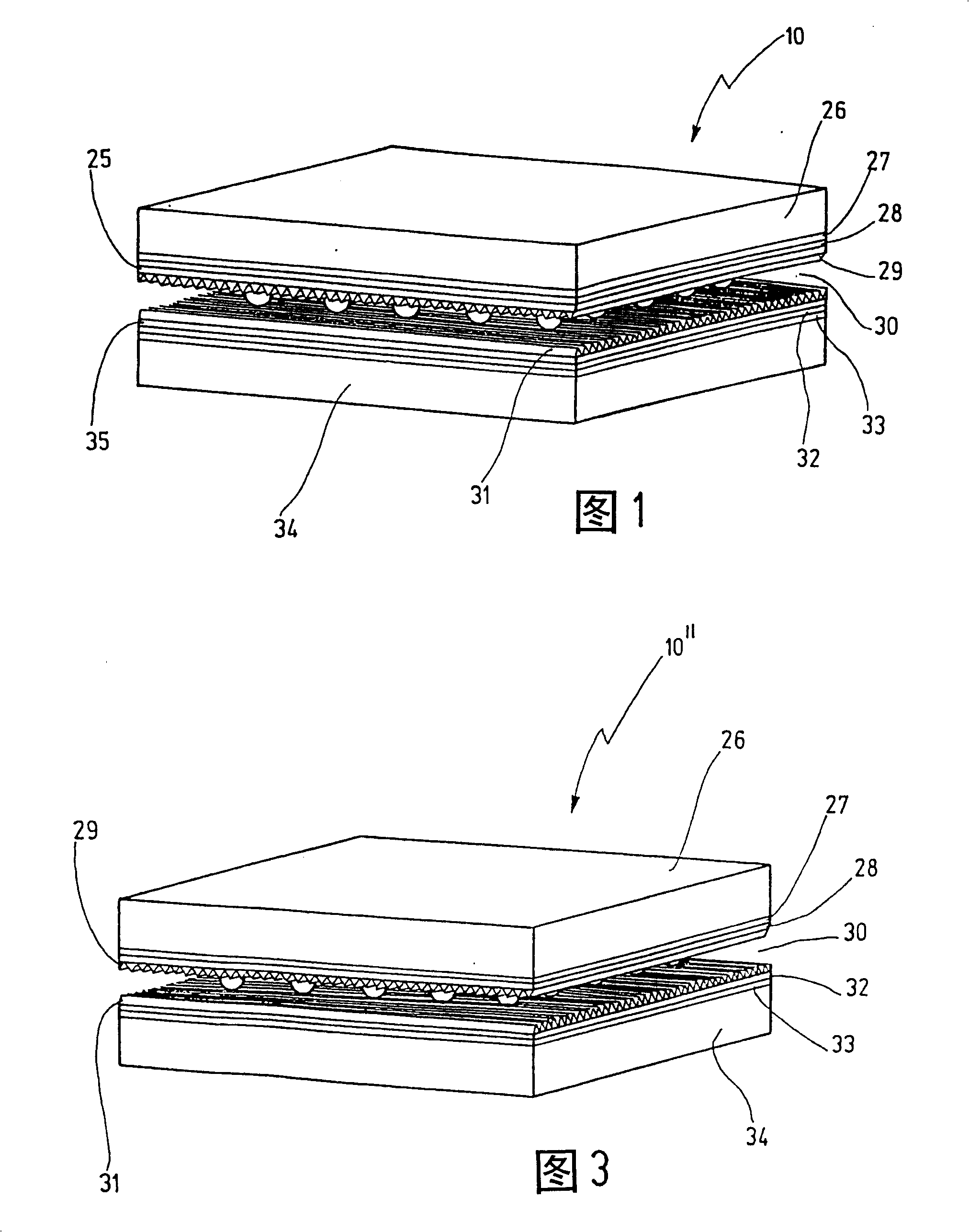
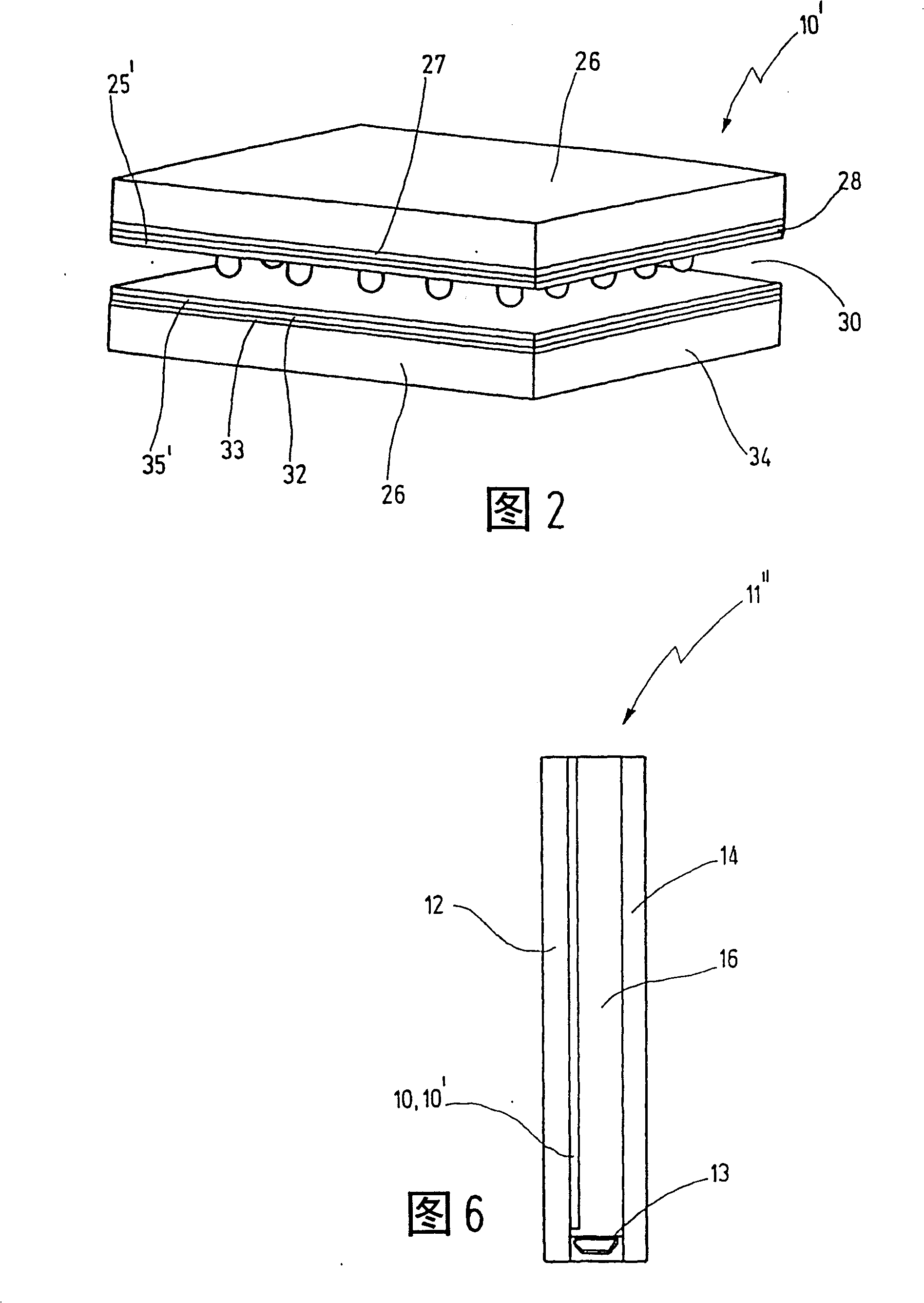
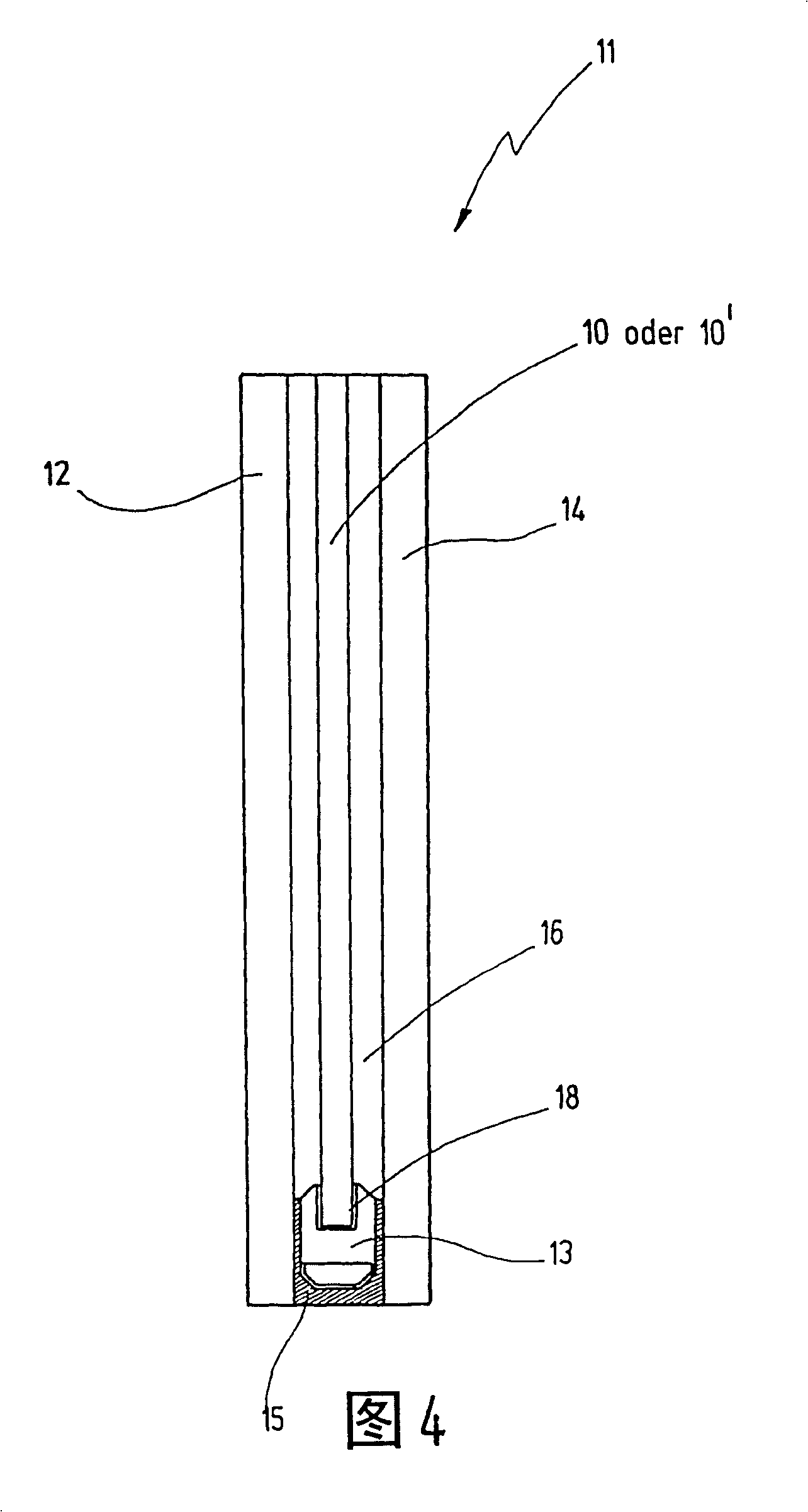
[0033] 1 shows schematically the structure of a steplessly electrically adjustable transmissive electro-optical element 10 with a liquid crystal layer 30 in the middle with spacers not shown in detail (so-called Spacer ), covered on both sides by an orientation layer 29 or 31. On top of the orientation layer 29 or 31 there is an insulator 28 or 32 which is covered by a transparent electrode 27 or 33 . A substrate medium 26 or 34 , which is either in the form of a glass substrate or a film substrate, is arranged on the two transparent electrodes 27 and 33 facing away from the liquid crystal layer 30 . In this respect, the structure of the electro-optical element 10 is substantially the same as that of a TN cell or an STN cell. In the illustrated exemplary embodiment, however, a light polarizer layer 25 or 35 is arranged between the insulator 28 or 32 and the alignment layer 29 or 31 . These light polarizer layers 25 and 35 serve to polarize the incident light before entering ...


PUM


Abstract

The invention relates to a continuously electrically switchable transmissive electrooptical element ( 10 ) for a glass pane arrangement ( 11 ) for windows, doors, partitions, fabade displays and the like, provided with a liquid crystal layer ( 30 ) upon whose both sides a transparent electrode ( 27, 33 ) is respectively arranged; also provided with a respective carrier substrate ( 26, 34 ). In order to ensure that the light polarizators are protected against external influences and to enable the transmissive electrooptical element ( 10 ) to be produced in an economical manner, a respective light polarisation layer ( 25, 35 ) is provided inside the element ( 10 ) of the liquid crystal layer ( 30 ) in an directly or indirectly adjacent position.

Description

technical field [0001] The invention relates to glazing for windows, doors, partition walls and building facades. Background technique [0002] Steplessly electrically adjustable light-transmittable elements in the form of so-called TN (Twisted Nematic) cells or STN (Super Twisted Nematic) cells are already known in the field of displays. In such cells or components using a liquid crystal layer, the light polarizer layer is arranged on the outer side of the corresponding substrate medium or on the substrate itself. A disadvantage of cells with polarizers arranged on the outside is that the polarizers cannot be protected against mechanical and physical influences in such cells or elements. Using a light polarizer with its own substrate medium makes the entire adjustable unit more expensive. Polarizers are sensitive to mechanical influences and to UV exposure and are a major cost factor, so the mentioned disadvantages are not acceptable. [0003] For glass installations who...

Claims


Application Information

Patent Timeline
Patent Type & Authority Patents(China)
IPC IPC(8): G02F1/1335E06B9/24G02B5/30
CPCE06B2009/2464G02F1/133528E06B9/24G02F2001/133565G02F1/133565
Inventor 维尔纳·索贝克瓦尔特·哈泽
Owner WERNER SOBEK INGE
Why Eureka
Try Eureka