
Socket for electronic module

A technology for electronic modules and sockets, which is applied in the field of sockets for electronic modules, can solve the problems of increased socket height, insufficient elasticity, inconvenient operation, etc., and achieve a firm locking effect

Inactive Publication Date: 2008-08-27
HIROSE ELECTRIC GROUP
View PDF5 Cites 0 Cited by
  • Summary
  • Abstract
  • Description
  • Claims
  • Application Information

AI Technical Summary

Problems solved by technology

[0008] In the socket of Patent Document 1, the locking arm extends from the upper surface of the bottom wall of the socket, so the length of the locking arm is below the height of the peripheral wall of the socket. In today's demand for thinner , the snap wrist does not ensure sufficient elasticity
That is to say, the elasticity of the claw of the locking wrist is not strong enough, so the insertion force when inserting the module needs to be very large, there will be too much force acting on the locking wrist, which may damage it
[0009] And if the height of the above-mentioned surrounding wall is kept and only the locking wrist is increased, the height of the socket will be increased only because of the locking wrist, which will cause inconvenience in operation.

Method used


Image

  • Socket for electronic module
  • Socket for electronic module
  • Socket for electronic module

Examples


Embodiment Construction

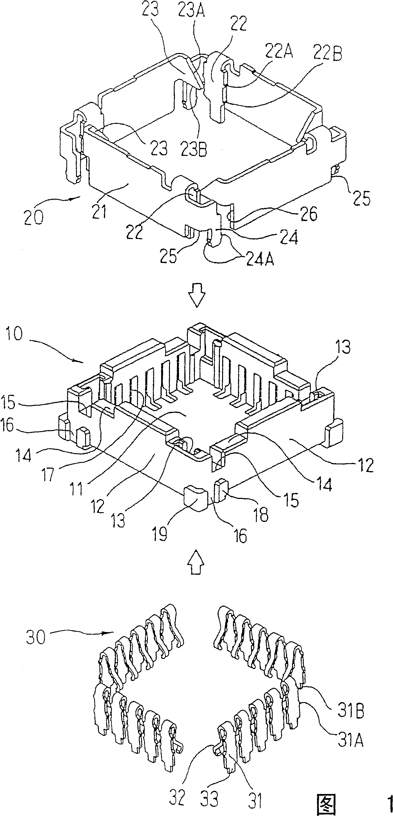
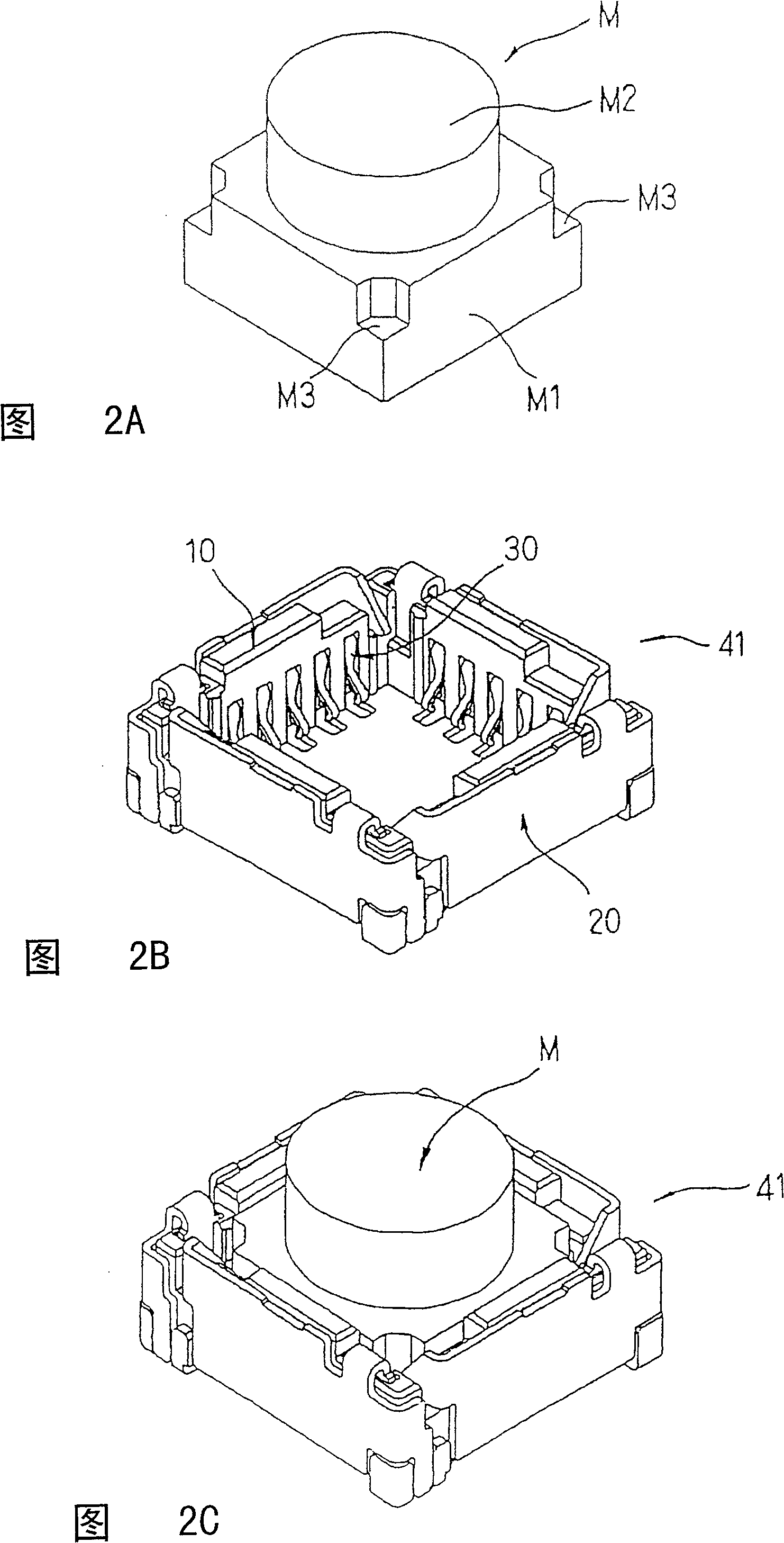
[0040] FIG. 1 is a perspective view of a separated state before assembly of each member constituting the socket for an electronic module according to one embodiment of the present invention.

[0041] In the figure, 10 is a casing made of an electrically insulating material, and a locking member 20 made of a metal plate and a terminal 30 are attached to the casing 10 .

[0042]The casing 10 has a plate-shaped bottom wall portion 11 and a quadrangular peripheral wall 12 vertically erected from the peripheral portion thereof. The surrounding wall 12 forms a space inside it as a housing part for housing the module, and the module is stored in the housing part, and the bottom wall part 11 restricts the further movement of the module in the housing direction. The wall portions on the four sides of the peripheral wall 12 are formed in the same manner in the circumferential direction. When the side of each wall portion is viewed from the outside, on the right side, the upper end surf...


PUM


Abstract

In the socket (41), a receiving section is formed by a circumferential wall (12) and a restricting section that defines the position of the counter module (M) when it is placed in the receiving section. The latching member (20) is formed by directly forming or attaching to the circumferential wall an elastic bar that extends in the circumferential direction of the circumferential wall. The latching member (20) has a securing section and a latching section (23) that elastically displaces outward of the circumferential wall by flexion of the elastic bar, and the securing section and the latching section are provided away from each other in the circumferential direction.

Description

technical field [0001] The invention relates to a socket for an electronic module. Background technique [0002] When connecting an electronic module with a built-in predetermined electronic circuit or parts to the circuit substrate, the module is not directly welded to the circuit substrate, but the socket is soldered to the circuit substrate, and then the above-mentioned module is inserted into the socket, The terminals are connected in contact with each other. This is in consideration of not causing damage due to the heat during welding when some parts in the module are weak to heat. [0003] Such a socket is disclosed in Patent Document 1, for example. [0004] The socket of Patent Document 1 such as Figure 13 As shown, it is made of insulating material, and the receiving recess 53 that can accommodate the electronic module M from above is formed by using the bottom wall 51 and the surrounding wall 52 . A plurality of terminals 54 are mounted on opposing wall portion...

Claims


Application Information

Patent Timeline
Patent Type & Authority Patents(China)
IPC IPC(8): H01R33/76H01R33/97H01R13/627H01R13/629H01R12/50H01R12/51
CPCH01R23/68H01R12/51G02B6/504H02G9/06
Inventor 和田俊太郎
Owner HIROSE ELECTRIC GROUP
Learn More