Eureka AIR delivers breakthrough ideas for toughest innovation challenges, trusted by R&D personnel around the world.

Positive-negative integral current lead structure with screw section and its manufacturing method

A current lead, spiral technology, applied in the field of low temperature and superconducting applications, can solve the problems of unbalanced temperature field, increased heat leakage of lead wires, unbalanced cooling airflow distribution, etc., achieve good symmetry and synchronization, and increase stability. , the effect of volume reduction

Inactive Publication Date: 2008-09-03
INST OF HIGH ENERGY PHYSICS CHINESE ACAD OF SCI +1
View PDF3 Cites 0 Cited by
  • Summary
  • Abstract
  • Description
  • Claims
  • Application Information

AI Technical Summary

Problems solved by technology

[0007] 2. For the current leads in actual operation, due to differences in the actual production process of the leads or some problems of the superconducting device itself, there are differences in the distribution of cooling airflow between the positive and negative leads or between different flow channels of the same lead. Unbalanced, resulting in an unbalanced temperature field
However, theoretical simulation calculations and experimental data show that the asymmetric distribution of airflow between the positive and negative leads and the uneven distribution of airflow between different channels of the same lead will greatly affect the normal operation of the current lead, making the temperature field distribution between the positive and negative leads Asymmetry or unbalanced temperature field between different runners of the same lead wire, thus causing the running state of the lead wire to deviate from the optimal point, increasing the heat leakage of the lead wire, and improving the instability of the lead wire operation

Method used


Image

  • Positive-negative integral current lead structure with screw section and its manufacturing method
  • Positive-negative integral current lead structure with screw section and its manufacturing method

Examples


Embodiment Construction

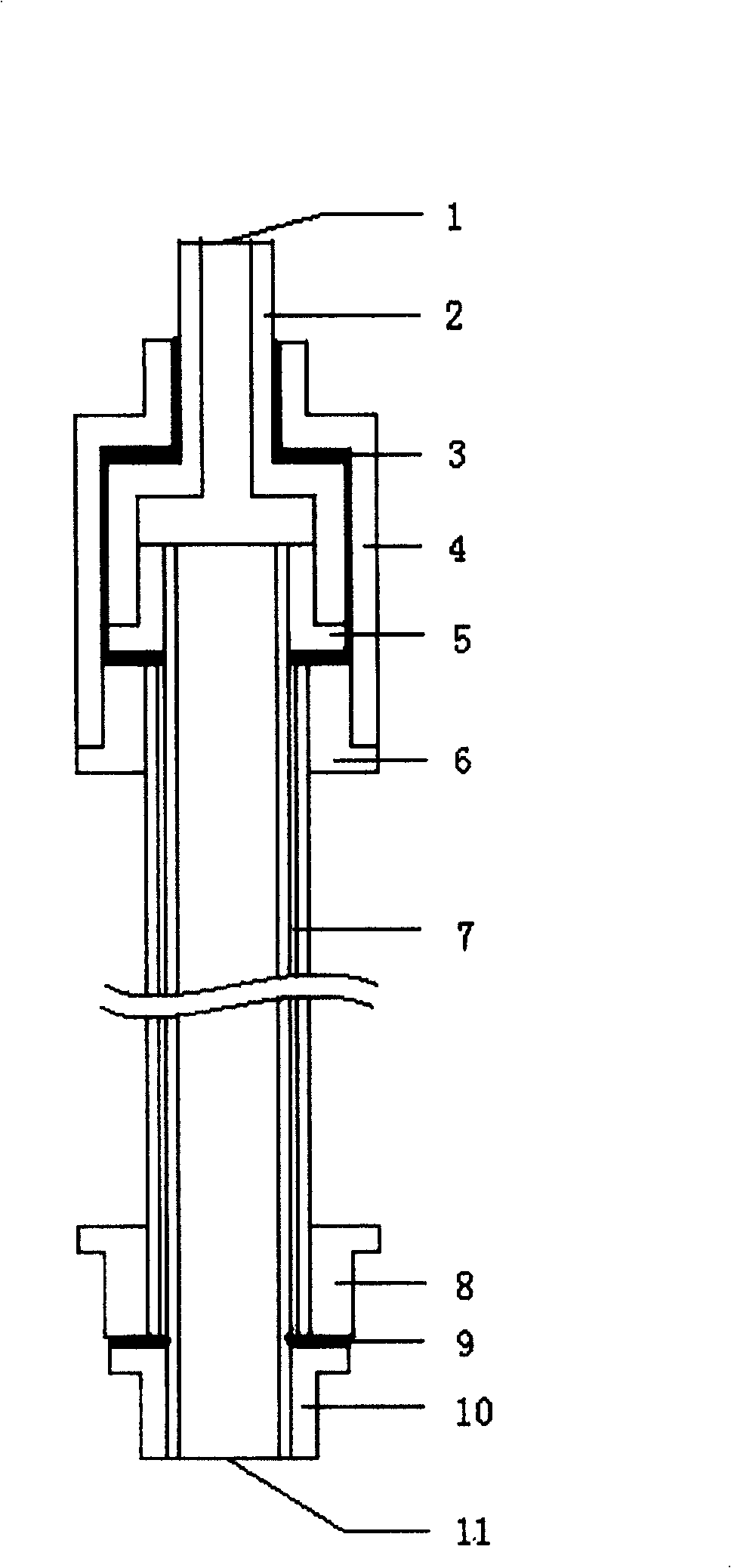
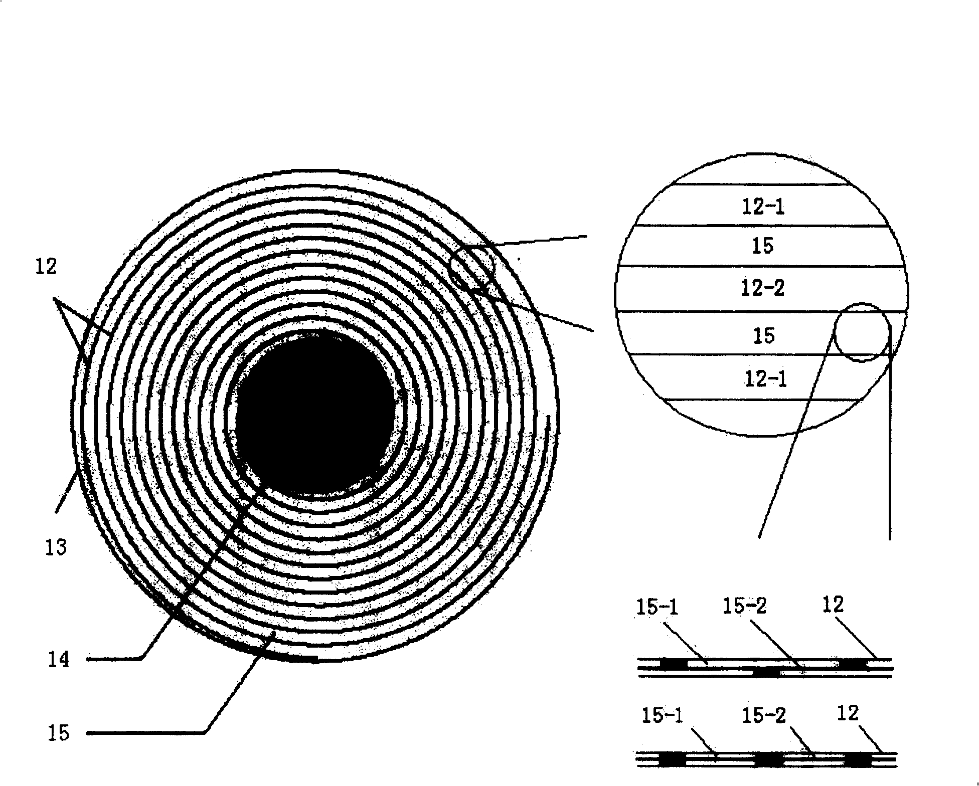
[0023] figure 1 It is a positive and negative integrated current lead overall structure with a spiral cross section. figure 2 Is the cross-sectional schematic diagram of the main part of the lead wire. Lead body 7 is composed of positive and negative copper coils 12, electrical insulating cylinder 13, electrical insulating rod 14, airflow channel 15-1 and electrical insulating layer 15-2, electrical insulating rod 14 is located in the middle, and electrical insulating cylinder 13 is on the outermost. The positive and negative copper coils 12 , the airflow channel 15 - 1 and the electrical insulating layer 15 - 2 are spirally wound around the electrical insulating rod 14 as the center.

[0024] The main body of the lead wire is composed of positive and negative copper coils, an airflow channel and an electrical insulation layer, an electrical insulation rod in the middle and an electrical insulation cylinder outside. The positive and negative copper coils carry the current o...


PUM


Abstract

This invention relates to a positive and negative integral current lead structure of a screw section and a method, in which, the lead main part is composed of screw like negative and positive copper roll, two gas flow channel &, electric insulation layer, an electric insulation rod at the center and an electric insulation rod at the ragged edge. The method includes: fixing two positive and negative copper plates, two gas flow channels &, electric insulation plate and one end of the two copper plates on the insulation rod and rolling up uniformly the rod with the two copper plates and the insulation plates, carving screw like slot on the copper post with the thickness of 10-20mm as the top and bottom rings of the lead, assembling the top and bottom rings and rolled copper plates, adding electric insulation material between the inside of the collecting bar of the negative top end and the positive and negative top end to solder the top ring and the collecting bar, wrapping the copper roll with insulation board and sealing the outer edge of the insulation board and the two ends with low temperature adhesive tape and adhesion.

Description

technical field [0001] The invention relates to the technical field of low temperature and superconducting applications. In particular, a positive and negative integrated current lead structure with a spiral cross section and a manufacturing method thereof. Background technique [0002] Current leads are an important component in many low-temperature superconducting systems. It is responsible for connecting the power supply at the room temperature side and the superconducting device at the low temperature side to ensure the normal power supply of the superconducting device. Because of the huge temperature difference between the two ends and the large amount of Joule heat generated when the power is turned on, a large amount of heat is brought into the low-temperature environment through the current lead. Therefore, in many superconducting systems, heat leakage from current leads is one of the most important heat sources in low-temperature environments. In order to reduce ...

Claims


Application Information

Patent Timeline
Patent Type & Authority Patents(China)
IPC IPC(8): H01L39/02H01B12/00H01B1/00
CPCY02E40/64Y02E40/60
Inventor 朱自安徐庆金易昌炼杨欢刘立强周谨黄世科张亮
Owner INST OF HIGH ENERGY PHYSICS CHINESE ACAD OF SCI
Why Eureka
Eureka Blog
Learn More