Processing method for groove of oscillating follower cylinder cam

A technology of cylindrical cam and processing method, which is applied in the direction of metal processing equipment, manufacturing tools, milling machine equipment, etc., can solve problems such as unseen technical solutions, errors, etc., to meet the requirements of high-precision products, eliminate dead spots, and eliminate motion track errors Effect

Inactive Publication Date: 2008-09-10
NINGBO INST OF TECH ZHEJIANG UNIV ZHEJIANG
View PDF4 Cites 3 Cited by
  • Summary
  • Abstract
  • Description
  • Claims
  • Application Information

AI Technical Summary

Problems solved by technology

[0005] (2) The error problem of the motion track; even after trimming, the follower can pass through the cam groove smoothly, but during the working process of the mechanism, since the swing follower deviates from the rotation axis of the cylindrical cam, it is not consistent with the designed motion. The track position deviates. When the machining of the cylindrical cam workpiece turns to a certain angle such as 50°, the tool also rotates through the angle relative to the cylindrical cam workpiece and moves to a certain position along the axis direction, and the cylindrical cam works to this position. When (50°), because the swing of the follower 2 deviates from the rotation axis of the cylindrical cam (see figure 2 ), the angle that the follower rotates relative to the cylindrical cam is not equal to 50°, such as figure 2 56° shown in , the position where the axis moves to is not the position where the tool moves in the axis direction when the cylindrical cam workpiece is rotated to 50°, which will cause the designed follower movement track to be different from the actual There is a large error between the movement trajectories of the follower
Consult relevant literature such as [5] Liu Defu et al. Several key issues in NC machining of cylindrical cams. Mechanical Transmission. 2003.3; [6] Li Jian et al. Research on NC machining methods for conical cam profiles. .2005.12, etc.; but there is no practical technical solution

Method used


Image

  • Processing method for groove of oscillating follower cylinder cam
  • Processing method for groove of oscillating follower cylinder cam
  • Processing method for groove of oscillating follower cylinder cam

Examples


Embodiment Construction

[0060] The present invention will be described in further detail below in conjunction with accompanying drawing and specific example, but the present invention is not limited to following embodiment (because the frequency that most of the objects marked with reference numerals in this embodiment, i.e. parts and coordinates, etc. occur too frequently High, if all add the mark then the file seems very cumbersome on the contrary, so, all marks all only mark when appearing for the first time, but the cylinder cam in the present embodiment, driven Part, tool, pendulum, unfolded surface, unfolded line, machining coordinates, and programming coordinates all refer to the same object).

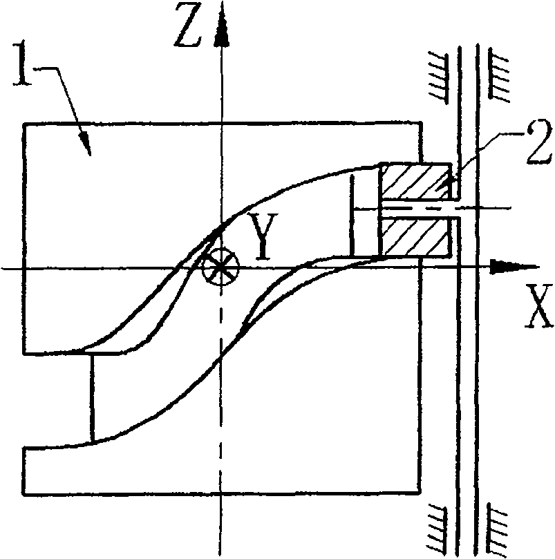
[0061] image 3 As shown, it is a linear follower cylindrical cam mechanism of the prior art, which can be programmed and processed by general plane expansion method (not discussed in the present invention).

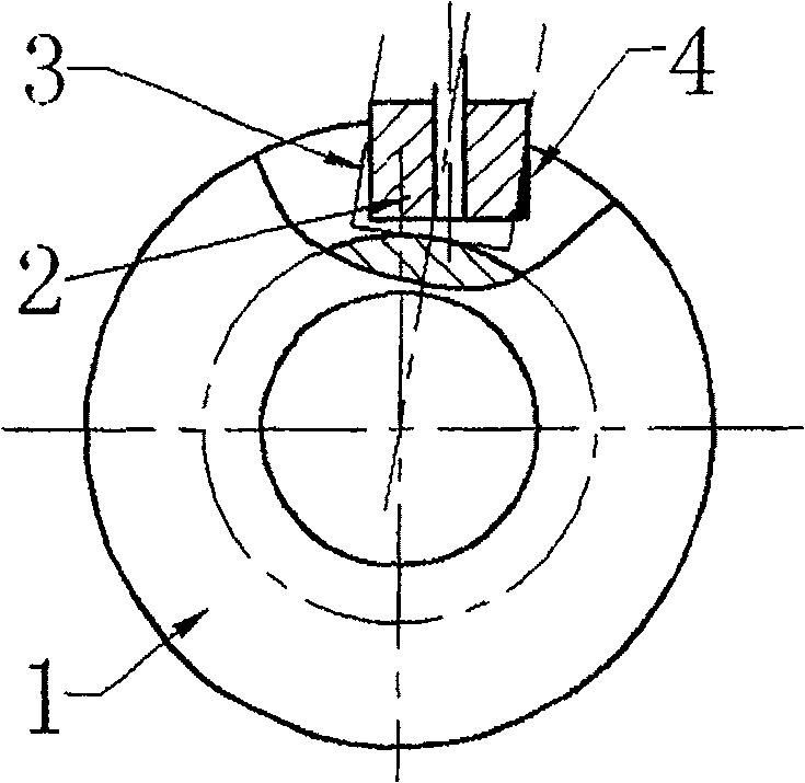
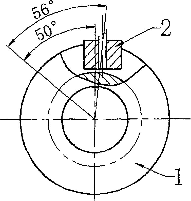
[0062] exist Figure 4 , Figure 5 Among them, the cylindrical cam axis is the Z axis, th...


PUM


Abstract

The invention relates to a method for processing the swing inactive cylinder cam groove, characterized in that the motion of swing inactive cylinder cam is divided into the arc swing along with the swing rod and the rotation relative to the cam, wherein, the arc swing can be decomposed into two mutually perpendicular straight motions in the swing plane as 3D motion, and the rotation relative to the cylinder cam is unfolded into the cylinder face that contacting the relation between the swing angle of swing rod and the rotation angle of cylinder cam as swing angle curvature onto the unfolded cylinder face, or projecting the relation between the displacement of swing inactive element and the rotation angle of cylinder cam as displacement curvature onto the unfolded cylinder face to obtain the 3D unfolded line; then based on the 3D unfolded line, processing the 3D blade track to be used in digit-control machine. The invention can avoid the error of general 2D unfolded method.

Description

technical field [0001] The invention belongs to the field of mechanical manufacturing, and relates to a processing method of mechanical parts, in particular to a processing method (including design and processing) of a cylindrical cam groove of a swing follower. Background technique [0002] Cylindrical cams are generally divided into two types: straight follower cylindrical cams and oscillating follower cylindrical cams. Many materials have analyzed and researched the design and processing of cylindrical cam grooves, such as [1] Xiao Yaoxian et al. Swing follower space cam CAM technology. Mechanical Science and Technology. 2002.5; [2] Gao Dongqiang et al. Using plane Practice of machining cylindrical cam with workpiece programming method. Journal of Shandong Institute of Light Industry. 2003.9; [3] Wei Sheng et al. Parametric design and numerical control machining of cylindrical cam. Precision manufacturing and automation. 2001.4; [4] Lu Jingui. Cam manufacturing technology...

Claims


Application Information

Patent Timeline
Patent Type & Authority Patents(China)
IPC IPC(8): F16H53/00G05B19/4099B23C3/28
Inventor 陈俊华
Owner NINGBO INST OF TECH ZHEJIANG UNIV ZHEJIANG
Why Eureka
Try Eureka