
Electronic water heater

A water heater and electronic technology, which is applied to water heaters, fluid heaters, lighting and heating equipment, etc., can solve the problems of unreasonable design of heating coils and water channels of power component circuits, endangering the personal safety of users, and low thermal efficiency of water heaters. To achieve the effect of easy to master and form large-scale production, long working time and large driving force

Inactive Publication Date: 2008-09-17
祝世权
View PDF6 Cites 0 Cited by
  • Summary
  • Abstract
  • Description
  • Claims
  • Application Information

AI Technical Summary

Problems solved by technology

The water heater with this structure not only has low thermal efficiency and small water flow, but also is prone to electric leakage, which endangers the personal safety of users.
In order to solve the safety problem, people use heating and use in stages, that is, the water is heated first, and then used after power off, which is extremely inconvenient to use.
In order to improve the thermal effect and safety, in recent years, some people have made electronic water heaters, which use low-frequency and power-frequency magnetic induction as heating heat sources. However, due to the unreasonable design of the power component circuit, drive circuit, heating coil and water channel, the energy-saving effect is not obvious, and the service life of the product is not obvious. Short, unstable performance, difficult processing technology, poor water discharge effect and other reasons, it is difficult to popularize and use in large quantities

Method used


Image

  • Electronic water heater
  • Electronic water heater
  • Electronic water heater

Examples


Embodiment 1

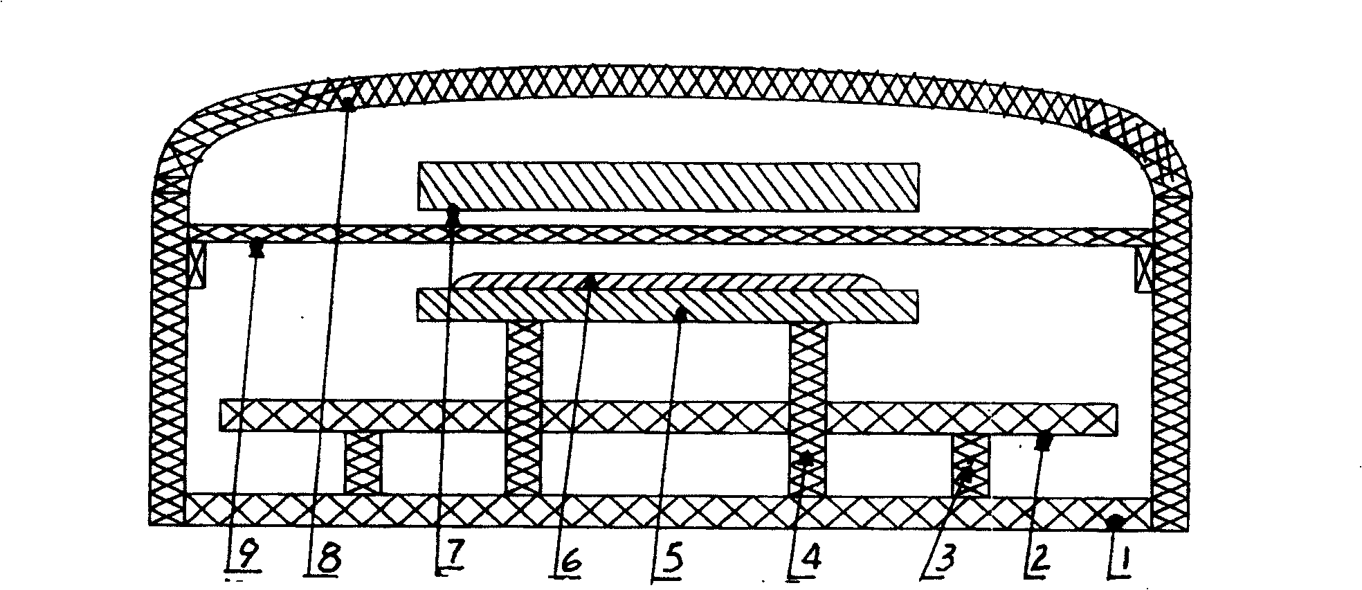
[0014] Example 1, such as figure 1 , 2 Design a water heater housing cover 8 shown in , 3, 4, 5, shell bottom plate 1 is affixed with base plate 2, inductance coil tray 5 assembly support column one end, and support column other end is affixed with circuit substrate 2 and inductance coil tray assembly 5, The number of supporting columns is set according to the needs. The present invention selects 4 substrate supporting columns 3 and 3 supporting columns 4 of the induction coil tray assembly. The side is provided with an induction coil wire inlet hole 15 and a wire outlet hole 16, and the lower half is provided with a circulating cooling water channel 11. The corresponding part of the inductance coil tray assembly is provided with a flat plate circulating water tank 7, which is provided with a folded water channel 12, and its inlet 13 is connected with the water inlet pipe, and the water outlet 14 is connected with the water outlet pipe. Water tank and heating induction coil ...


PUM


Abstract

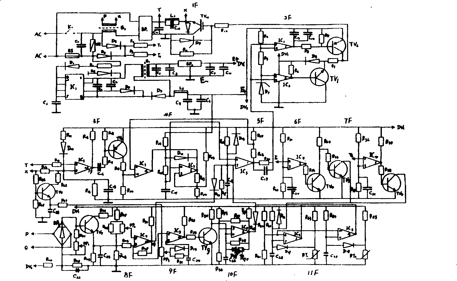
The invention discloses an electronical water heater, comprising outer cover (8), support bar (3) connected with outer cover (1) and base plate (2), and electronic circuit (1F-11F). Power module circuit is designed to power amplifier circuit comprising one IGBT pipe and damped diode. One end of it is connected with driving circuit by resistance and the other end is connected with heating induction coil. Driving circuit comprises triodes TV1, TV2; resistances R4-R9; capacitances C13, C14; diodes D8, D7; a power transformer B1, a power circuit BP2, a power ic IC1, and a driver ic IC2. The wire diameter of heating induction coil is 0.2-0.3mm and corresponded to flat cycling tank. Microcrystal glass clapboard is set between them. It is provided with high efficiency, long service life, good safety and easy production.

Description

technical field [0001] The invention relates to an electric heating device, in particular to an electronic water heater. Background technique [0002] The traditional electric water heater is composed of a water tank and an electric heating tube in it. The electric heating tube is a metal tube, and the heating wire is located in the center of the metal tube. The heat generated by the heating wire indirectly heats the water through the metal tube for people to use. The water heater with this structure not only has low thermal efficiency and small water flow, but also easily generates electric leakage, which endangers the personal safety of users. In order to solve the safety problem, people use heating and use in stages, that is, the water is heated first, and then used after power off, which is extremely inconvenient to use. In order to improve the thermal effect and safety, in recent years, some people have made electronic water heaters, which use low-frequency and power-f...

Claims


Application Information

Patent Timeline
Patent Type & Authority Patents(China)
IPC IPC(8): F24H1/10
Inventor 祝世权
Owner 祝世权
Learn More