
Method for coiling optical fiber in communication equipment

A technology of communication equipment and optical fiber, which is applied in the field of optical fiber coiling, can solve the problems of optical fiber accumulation, difficulty in scheduling, and long signal interruption time, and achieve the effects of short signal interruption time, easy removal, and space saving

Inactive Publication Date: 2008-09-24
徐培军
View PDF4 Cites 0 Cited by
  • Summary
  • Abstract
  • Description
  • Claims
  • Application Information

AI Technical Summary

Problems solved by technology

[0011] The purpose of the present invention is to provide a method for coiling optical fibers in communication equipment, which solves the technical problems in the background technology that optical fibers are piled up and twisted, scheduling is difficult, signal interruption time is long during scheduling, and scrapped optical fibers cannot be removed.

Method used


Image

  • Method for coiling optical fiber in communication equipment
  • Method for coiling optical fiber in communication equipment
  • Method for coiling optical fiber in communication equipment

Examples


Embodiment Construction

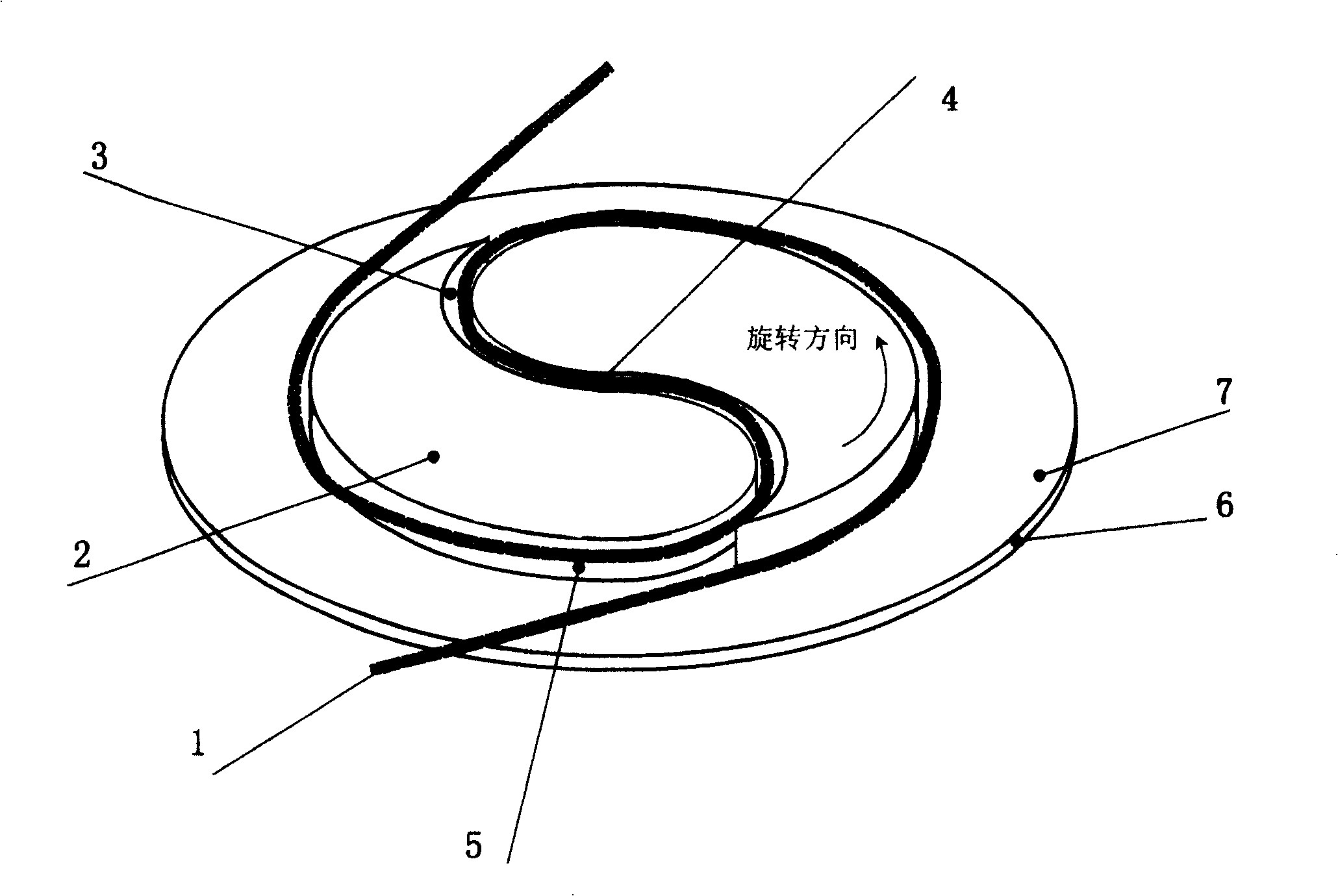
[0031] see figure 1 , the implementation of the present invention comprises the following steps:

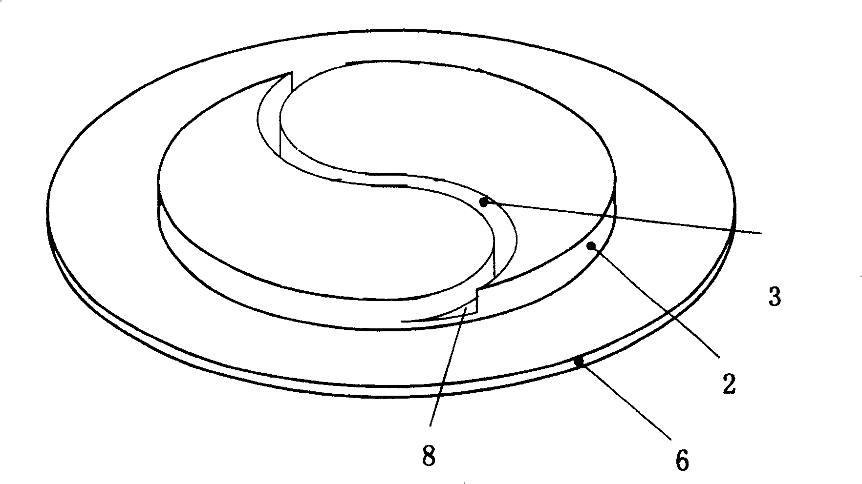
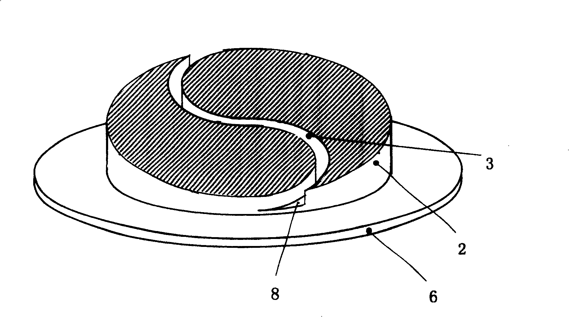
[0032] 1).Fiber insertion: After the optical fiber 1 enters the communication equipment, the central section of the optical fiber 1 to be stored is embedded in the fiber insertion groove 3 of the fiber column 2;

[0033] 2). Make the central section of the optical fiber 1 form a smooth curve with an odd number of inflection points 4 in the fiber insertion groove 3;

[0034] 3). Guide the optical fiber 1 to the disk fiber side 5 of the disk fiber column 2: make the optical fiber 1 embedded in the fiber embedding groove 3 of the disk fiber column 2 smoothly transition to the disk fiber side 5 of the disk fiber column 2;

[0035] 4). Disk fiber: rotate the disk fiber column 2, so that the optical fibers 1 on both sides of the central section are wound on the disk fiber column 2 in the same direction along the smooth curve.

[0036] When inserting the fiber, in order to make the o...


PUM


Abstract

The coiling method for optical fiber in communication equipment comprises: after putting optical fiber into communication equipment, embedding the center segment of fiber into the fiber-embed slot on fiber-coil column to form smooth curve with odd inflection points; leading the optical fiber transfer the fiber smooth segment to side of the column; rotating the column to make the fiber on center segment ends twist the column with same direction. This invention solves the problem in current technology, convenient to dispatch and operate, saves space, and can continual coil accurately to store the optical fiber and save space.

Description

technical field [0001] The invention relates to a method for coiling optical fibers in communication equipment, in particular to a method for coiling and storing pigtails, optical fibers and fiber jumpers in communication equipment. Background technique [0002] In the field of communication, pigtails, optical fibers, and jumpers that connect various communication devices or connecting devices to optical cables are collectively referred to as optical fibers. Modern communication equipment rooms are full of communication equipment, and the number of optical fibers connected to them is huge. One end of the optical fiber is connected to communication equipment such as transmission equipment and switches, and the other end is connected to the optical distribution device ODF. The optical fiber is uniformly dispatched in the optical distribution equipment in order to connect different equipment to form the required communication network. A set of large-capacity optical distribut...

Claims


Application Information

Patent Timeline
Patent Type & Authority Patents(China)
IPC IPC(8): G02B6/36G02B6/44H04B10/12
Inventor 王慧峰
Owner 徐培军
Learn More