Transmission balance mechanism of needling machine

A technology of balancing mechanism and acupuncture machine, applied in acupuncture machine, textile and papermaking, non-woven fabric, etc., can solve the problems of unsuitable structure, limitation, machine can not work normally, etc., to increase the frequency of acupuncture and improve the efficiency Effect

Inactive Publication Date: 2008-11-05
常熟市双龙无纺设备有限公司
View PDF5 Cites 2 Cited by
  • Summary
  • Abstract
  • Description
  • Claims
  • Application Information

AI Technical Summary

Problems solved by technology

However, for the currently widely used acupuncture machines with single main shaft, single connecting rod, single movable needle beam, and single needle plate, the structure of the reference literature cannot be applied.
[0004] Theoretically speaking, the rotation speed of ordinary needle looms with a relatively simple structure and low cost, which are currently in service and are in service with single-spindle drive, should not be limited. The highest speed of the machine is only at the level of 600-800n / min
Because, when the speed is less than or equal to 600n / min, the centrifugal force generated by the configuration of the balance weight can be offset by the machine's own weight, so that the acupuncture machine can work normally; Work, but there is obvious vibration, which affects the quality of the product; when it is greater than 800n / min, the vibration is serious and the machine cannot work normally

Method used


Image

  • Transmission balance mechanism of needling machine
  • Transmission balance mechanism of needling machine

Examples


Embodiment Construction

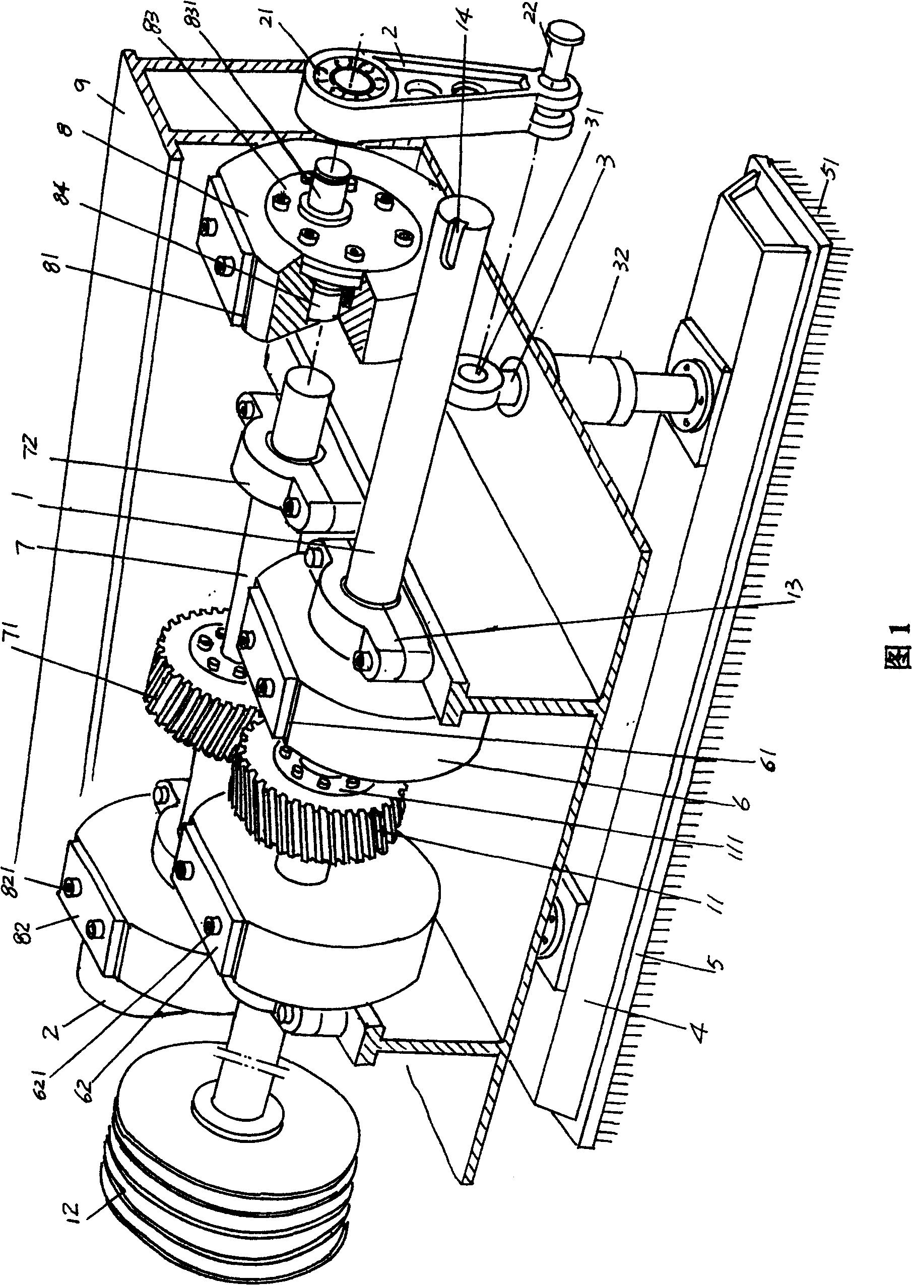
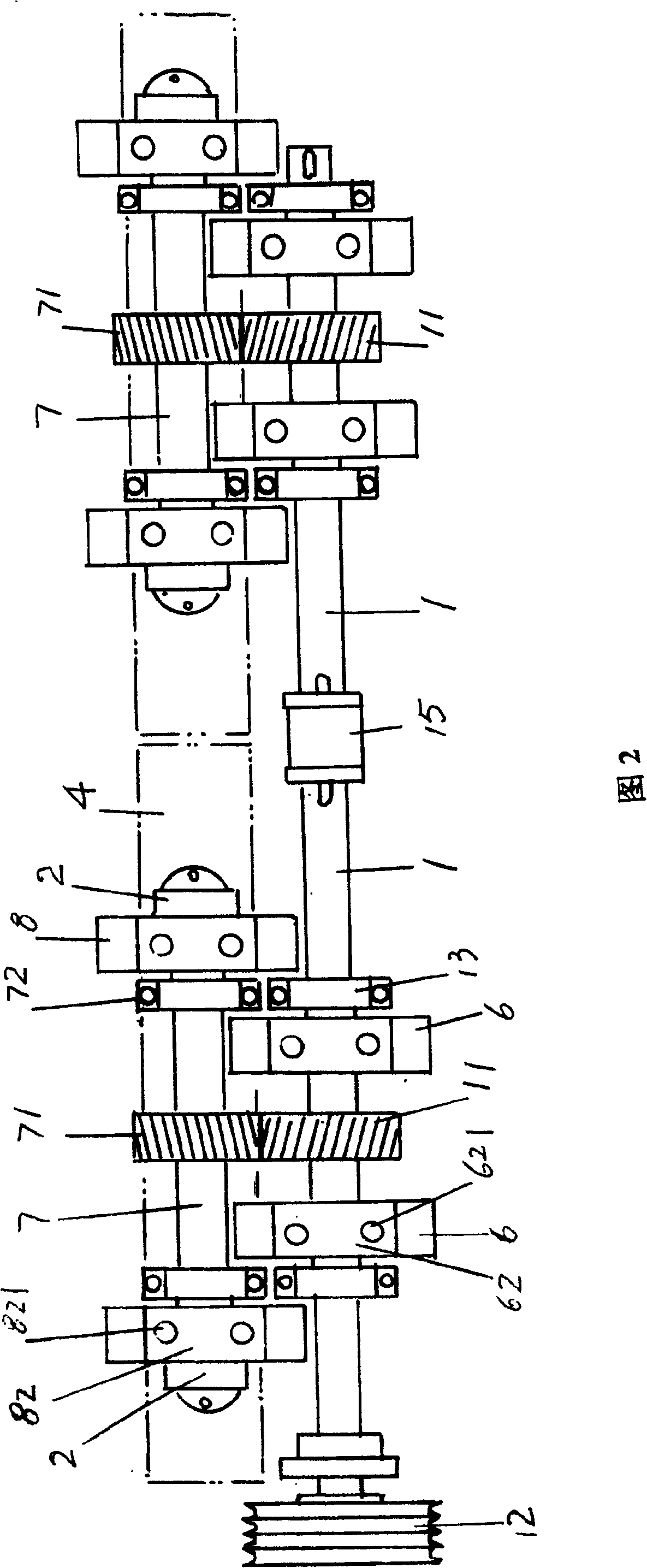
[0018] In Fig. 1 and Fig. 2, in order to facilitate understanding applicant has provided frame 9 in Fig. 1, main shaft 1 is pivoted on frame 9 by a pair of main shaft bearing seat 13, at one end of main shaft 1 (illustration The left end) is fixed with a pulley 12, and the other end of the main shaft 1 is preset with a connecting shaft groove 14. It goes without saying that the function of connecting shaft groove 14 is to connect the main shaft 1 of another unit, which can be relieved from FIG. 2 and realized with connecting sleeve 15 . The connecting rod 2 is changed from the setting position in the prior art, that is, in the prior art, it is connected to the main shaft 1 through a large-diameter deep groove bearing, but in the structure of the present invention, it is arranged on the countershaft balance wheel through a cylindrical bearing 21. 8 on. First fix the auxiliary shaft balance wheel 8 with the auxiliary shaft 7 through the expansion sleeve 84, then connect the upp...


PUM


Abstract

The present invention relates to a needle-punching machine transmission equalizing mechanism, belonging to the field of nonwoven machinery technology. It includes the following several components: main shaft, connecting rod, pushing rod, movable needle beam, needle plate and main shaft balance wheel. It is characterized by that on the main shaft also is set a main shaft gear, said needle-punching machine transmission equalizing mechanism has a pair of main shaft balance wheels, on every main shaft balance wheel a first edge-cutting plane is formed respectively, on first edge-cutting plane a first balance plate is set; on the position parallel to said main shaft an auxiliary shaft is pivoted, on the auxiliary shaft a pair of auxiliary shaft balance wheels which respectively are equipped with an adjustable eccentric block is fixedly placed, on every auxiliary shaft balance wheel a second edge-cutting plane is respectively formed, on said second edge-cutting plane a second balance plate is set, and on the auxiliary shaft a driven gear also is fixedly placed; the upper end of said connecting rod is connected on the auxiliary shaft balance wheel, and its lower end is connected with pushing rod. Said invention can raise needle-punching frequency of needle plate and can improve nonwoven fabric production efficiency.

Description

technical field [0001] The invention relates to a transmission balance mechanism of an acupuncture machine, in particular to a transmission balance mechanism of an acupuncture machine with a single shaft transmission of a single link, a single needle beam and a single needle plate, belonging to the technical field of non-woven machinery. Background technique [0002] In non-woven machinery, the structure of the transmission mechanism of the movable needle beam of the single-axis transmission acupuncture machine is composed of a main shaft equipped with a balance weight, a connecting rod, a push rod, a movable needle beam, and a needle plate. The block is fixed on the main shaft, the main shaft is pivoted on the frame, a belt pulley is fixed at one end of the main shaft, and the main shaft is rotated by means of the belt through the pulley through the power, the other end of the main shaft is connected to the upper end of the connecting rod, and the lower end of the connecting...

Claims


Application Information

Patent Timeline
Patent Type & Authority Patents(China)
IPC IPC(8): D04H18/00D04H18/02
Inventor 王建忠姚彩明
Owner 常熟市双龙无纺设备有限公司
Why Eureka
Try Eureka