
High Frequency Alignment Stimulation Machine

It is a high-frequency alignment technology, which is applied in the field of high-frequency alignment alignment, and can solve problems such as large reciprocating inertial force, large vibration excitation, and large eccentric wheel size.

Active Publication Date: 2017-08-08
SHANTOU SANHUI NONWOVEN MACHINERY FACTORY
View PDF14 Cites 1 Cited by
  • Summary
  • Abstract
  • Description
  • Claims
  • Application Information

AI Technical Summary

Problems solved by technology

[0007] However, since the above-mentioned upper transmission shaft assembly and the lower transmission shaft assembly are composed of several eccentric wheels installed on the central shaft, the eccentric wheels are larger in size, their rotating mass is heavier, their reciprocating inertial force is larger, and the amount of vibration aroused is quite large. , so the acupuncture frequency of the acupuncture mechanism is greatly restricted (the highest acupuncture frequency of most acupuncture mechanisms can only reach 1000rnp / min), which restricts the improvement of the quality and production efficiency of nonwovens, and produces more noise

Method used


Image

  • High Frequency Alignment Stimulation Machine
  • High Frequency Alignment Stimulation Machine
  • High Frequency Alignment Stimulation Machine

Examples


Embodiment Construction

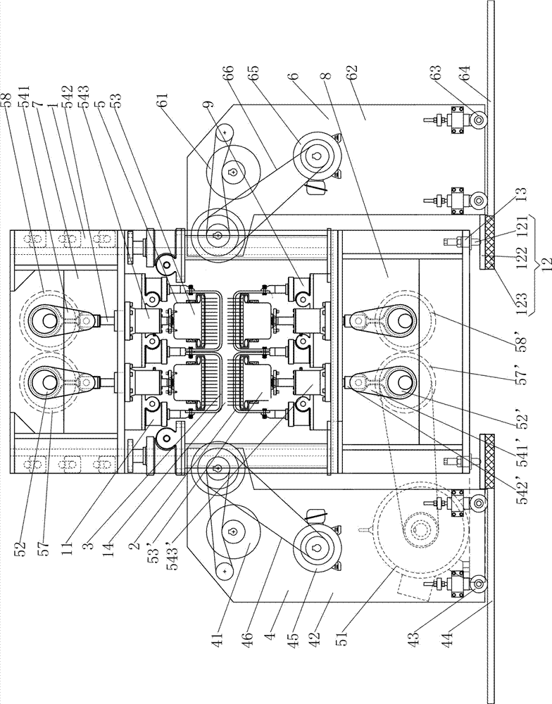
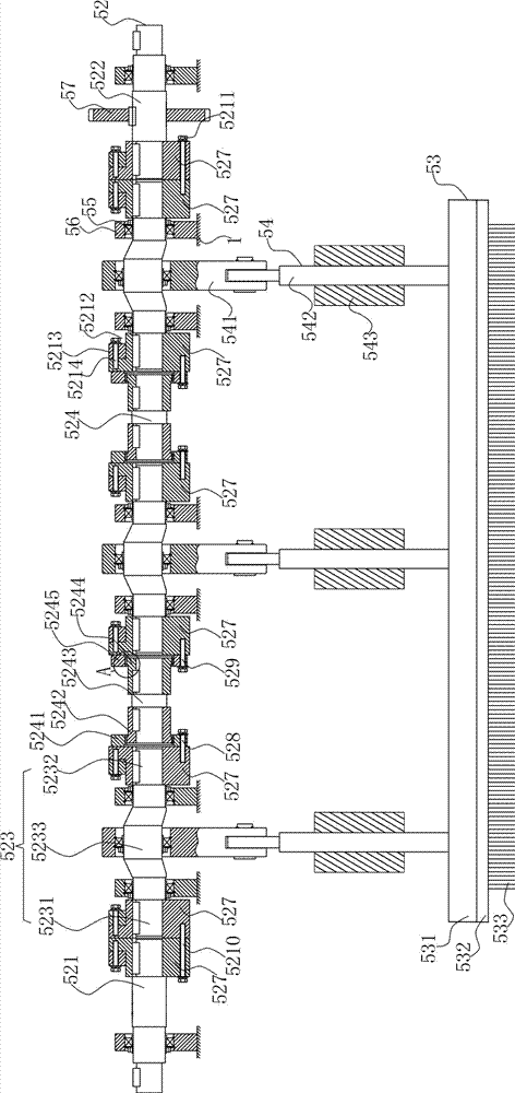
[0040] like figure 1 As shown, this high-frequency co-located punching machine includes a frame 1, a mesh feeding mechanism 4, a lower stripping mesh plate 2, an upper stripping mesh plate 3, a needle punching mechanism 5 and a pulling mechanism 6; the upper stripping mesh plate 3 is located at the bottom Above the screen stripping plate 2; the acupuncture mechanism 5 includes a needling driving device, an upper acupuncture mechanism and a lower acupuncture mechanism, the upper acupuncture mechanism is located above the upper stripping screen plate 3, and the lower acupuncture mechanism is located below the lower stripping screen plate 2 ; The net feeding mechanism 4 is located in front of the acupuncture mechanism 5, and the pulling mechanism 6 is located in the rear of the acupuncture mechanism 5.

[0041] like figure 1 and figure 2As shown, the upper acupuncture mechanism includes two upper drive shaft assemblies 52 side by side and two upper needle assemblies 53 side by...


PUM


Abstract

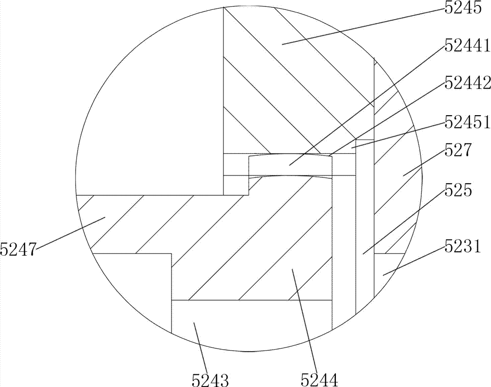
A high-frequency co-location punching machine, including a frame, a net feeding mechanism, a lower web stripping board, an upper web stripping board, a needling mechanism and a pulling mechanism; the upper needling mechanism includes two upper drive shaft assemblies and two upper The needle assembly, the lower acupuncture mechanism includes two lower transmission shaft assemblies and two lower needle assemblies, and is characterized in that: the upper transmission shaft assembly and the lower transmission shaft assembly each include a left half shaft, a right half shaft and a plurality of crankshafts, The crankshaft includes two shaft heads and a boss integrally connected. The boss is cylindrical and its center line deviates from the axis of the shaft head; one crankshaft in the upper transmission shaft assembly corresponds to an upper lifting transmission mechanism, and the upper shaking in the upper lifting transmission mechanism The upper end of the arm is socketed on the boss of the corresponding crankshaft; one crankshaft in the lower transmission shaft assembly corresponds to a lower lifting transmission mechanism, and the lower end of the lower rocker arm in the lower lifting transmission mechanism is socketed on the boss of the corresponding crankshaft. The invention has high acupuncture frequency and small vibration excitation, which is beneficial to improve production efficiency and product quality.

Description

technical field [0001] The invention relates to an acupuncture machine, in particular to a high-frequency parallel punching machine. Background technique [0002] Acupuncture is one of the most important processing techniques for nonwovens. There are many types of acupuncture machines, one of which is the iso-punching machine. [0003] The co-located punching machine usually includes a frame, a mesh feeding mechanism, a lower stripping mesh plate, an upper stripping mesh plate, a needle punching mechanism and a pulling mechanism; the upper stripping mesh plate is above the lower stripping mesh plate; the needle punching mechanism includes a needle punching drive device , The upper acupuncture mechanism and the lower acupuncture mechanism, the upper acupuncture mechanism is located above the upper stripping screen plate, and the lower acupuncture mechanism is located below the lower stripping screen plate; Stab at the rear of the mechanism. The gap between the lower strippi...

Claims


Application Information

Patent Timeline
Patent Type & Authority Patents(China)
IPC IPC(8): D04H18/02
Inventor 杨长辉
Owner SHANTOU SANHUI NONWOVEN MACHINERY FACTORY
Learn More