Air conditioner for vehicle capable of preventing inverter overheating

An air conditioner and overheating technology, which is applied to irreversible cycle compressors, vehicle components, air handling equipment, etc., can solve the problems of motor drive unit temperature rise, pressure rise, and refrigerant flow path damage

Active Publication Date: 2008-11-12
DENSO CORP
View PDF4 Cites 6 Cited by
  • Summary
  • Abstract
  • Description
  • Claims
  • Application Information

AI Technical Summary

Problems solved by technology

As a result, the current of the motor is also increased, and the temperature on the side of the motor drive unit is also increased accordingly, and the cooling effect of the refrigerant in the motor drive unit can no longer be obtained
In addition, if an attempt is made to supply refrigerant to the condenser at high pressure, the pressure at the refrigerant inlet end of the condenser may rise excessively, and the pressure will destroy the flow path of the refrigerant, and the refrigeration cycle will no longer function.
[0009] In addition, when the total amount of heat exchanged in the evaporator is small, the flow rate of the condenser to the evaporator is increased to cool the evaporator excessively, and the condensed water freezes, so the refrigeration cycle may no longer function

Method used


Image

  • Air conditioner for vehicle capable of preventing inverter overheating
  • Air conditioner for vehicle capable of preventing inverter overheating
  • Air conditioner for vehicle capable of preventing inverter overheating

Examples


no. 1 example

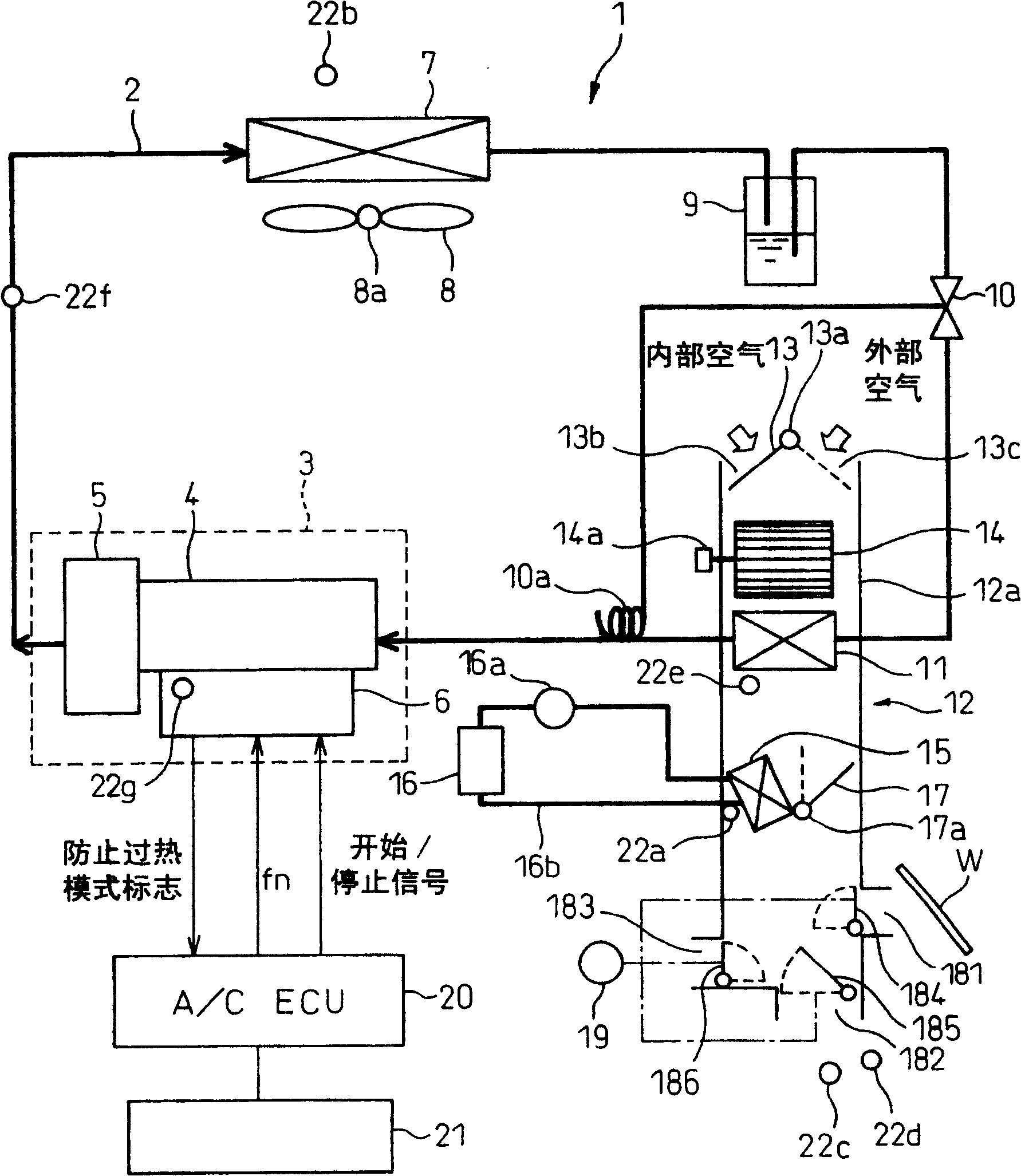
[0037] figure 1 It is a block diagram showing the general structure of the vehicle air conditioner in the present invention. The refrigeration cycle 2 of the air conditioner for the vehicle 1 includes an electric compressor 3 that sucks in, compresses, and discharges refrigerant. The electric compressor 3 includes an electric motor 4 and a compression mechanism 5 driven by the electric motor 4, both of which are integrally formed in one unit. Specifically, the electric motor 4 is a three-phase AC motor, and the compression mechanism 5 is, for example, a well-known screw-type compression mechanism. Thus, the compression mechanism 5 can continuously change the discharge amount in the range of 0% to 100% according to the rotation speed of the electric motor 4 .

[0038] By variably controlling the frequency of the three-phase AC power supplied to the motor 4 by using the inverter 6 as a motor drive unit, the rotation speed of the motor 4 can be controlled at a rotation speed pr...

no. 2 example

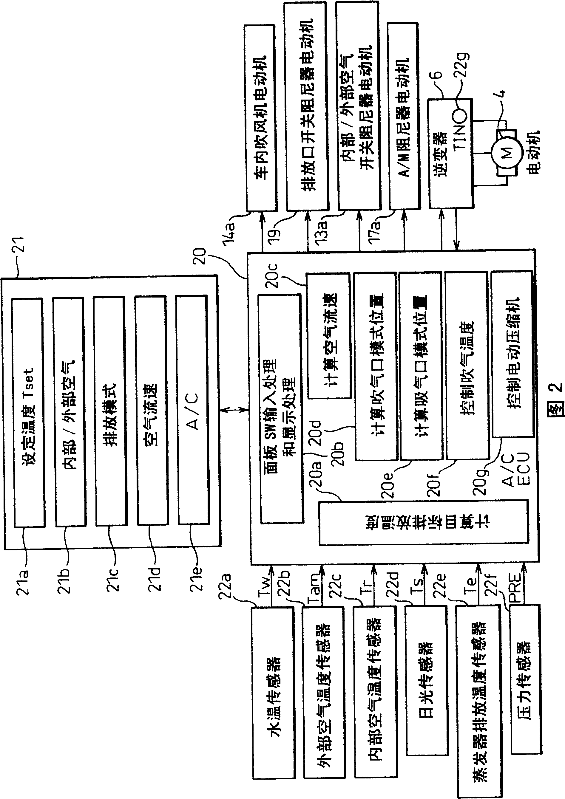
[0111] In the above-mentioned first embodiment, the air conditioner control unit 20 judges whether the inverter 6 is working in the overheating prevention mode by detecting the overheating prevention mode flag output by the inverter 6, but in the second embodiment, the inverter 6 The temperature TIN detected by the inverter temperature sensor 22g is output to the air conditioner control unit 20, and the air conditioner control unit 20 judges the operating state of the inverter 6 based on the inverter temperature TIN from the inverter 6.

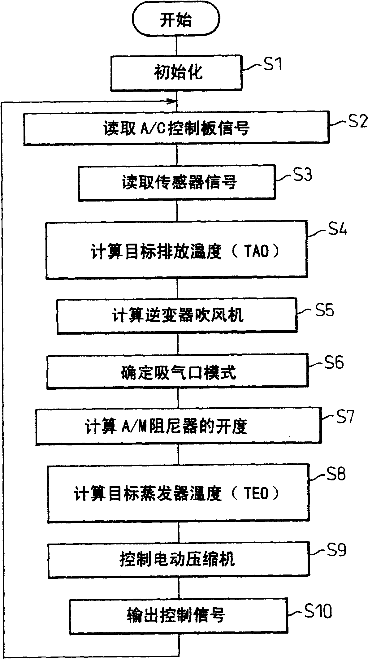
[0112] Figure 9 Showing the operation judgment procedure of the inverter 6 in the air conditioner control unit 20 of the second embodiment, FIG. 10 shows the control procedure of the inverter 6 in the second embodiment. As in the operation judging program in the first embodiment ( Figure 7 ) is the same as in the control program (Fig. 8), the same process is attached with the same sign, which will not be described here. In addition, the m...


PUM


Abstract

An inverter 6 that drives an electric motor 4 of the electric compressor 3 operates in a protection-against-overheat mode, in which the electric motor is driven at a rotational speed for protection against heat different from a rotational speed specifying value from an air conditioning control unit 20 , in order to ensure the flow rate of the refrigerant and cool the inverter itself when the temperature detected by an inverter temperature sensor 22 g exceeds a predetermined value. At this time, if the refrigerant pressure increases or the evaporator discharge temperature falls, the air conditioning control unit stops the protection-against-overheat mode operation of the inverter and directs the inverter to forcedly stop the electric motor. Due to this, an excessive increase in the refrigerant pressure and evaporator freezeing can be prevented, and thus the function of the refrigerating cycle can be protected.

Description

technical field [0001] The present invention relates to a vehicle air conditioner having a protection function of protecting a cooling system by using an electric compressor. Background technique [0002] According to the prior art, the electric compressor in the known vehicle air conditioner has a compressor for absorbing and discharging refrigerant, a compressing part for compressing the sucked refrigerant into the compressor, an electric motor for driving the compressing part, and a motor for driving and controlling the compressor. A motor-driven unit of an electric motor, the known air conditioner is used in a refrigeration cycle with a condenser, a pressure reducing device and an evaporator. [0003] In such a vehicle air conditioner, the temperature of the motor drive unit that drives and controls the motor compressor rises due to the heat generated by the motor drive unit's own operation and the heat discharged from other heat sources such as the engine, and includes ...

Claims


Application Information

Patent Timeline
Patent Type & Authority Patents(China)
IPC IPC(8): F04B49/00F04B35/04F04B49/10B60H1/32F25B1/00F25B45/00F25B49/00F25B49/02
CPCB60H2001/3292B60H2001/3261F25B49/025B60H1/3225B60H2001/3238F25B2700/21175B60H1/3214F25B2700/1931F25B2600/021B60H2001/3272F25B2700/21161B60H1/00978
Inventor 大村充世穗满敏伸
Owner DENSO CORP
Why Eureka
Try Eureka