Heating device for components

A technology for equipment and components, applied in the field of equipment for heating components, can solve the problems of high cost and complicated pit construction technology, and achieve the effects of speeding up assembly, shortening time, and saving test time

Inactive Publication Date: 2008-11-12
WILHELM HENDRICH VAKUUMANLAGEN & K G
View PDF7 Cites 0 Cited by
  • Summary
  • Abstract
  • Description
  • Claims
  • Application Information

AI Technical Summary

Problems solved by technology

[0007] The disadvantage of this construction is that the pit is technically complex to construct and therefore expensive for the user

Method used


Image

  • Heating device for components
  • Heating device for components
  • Heating device for components

Examples


Embodiment Construction

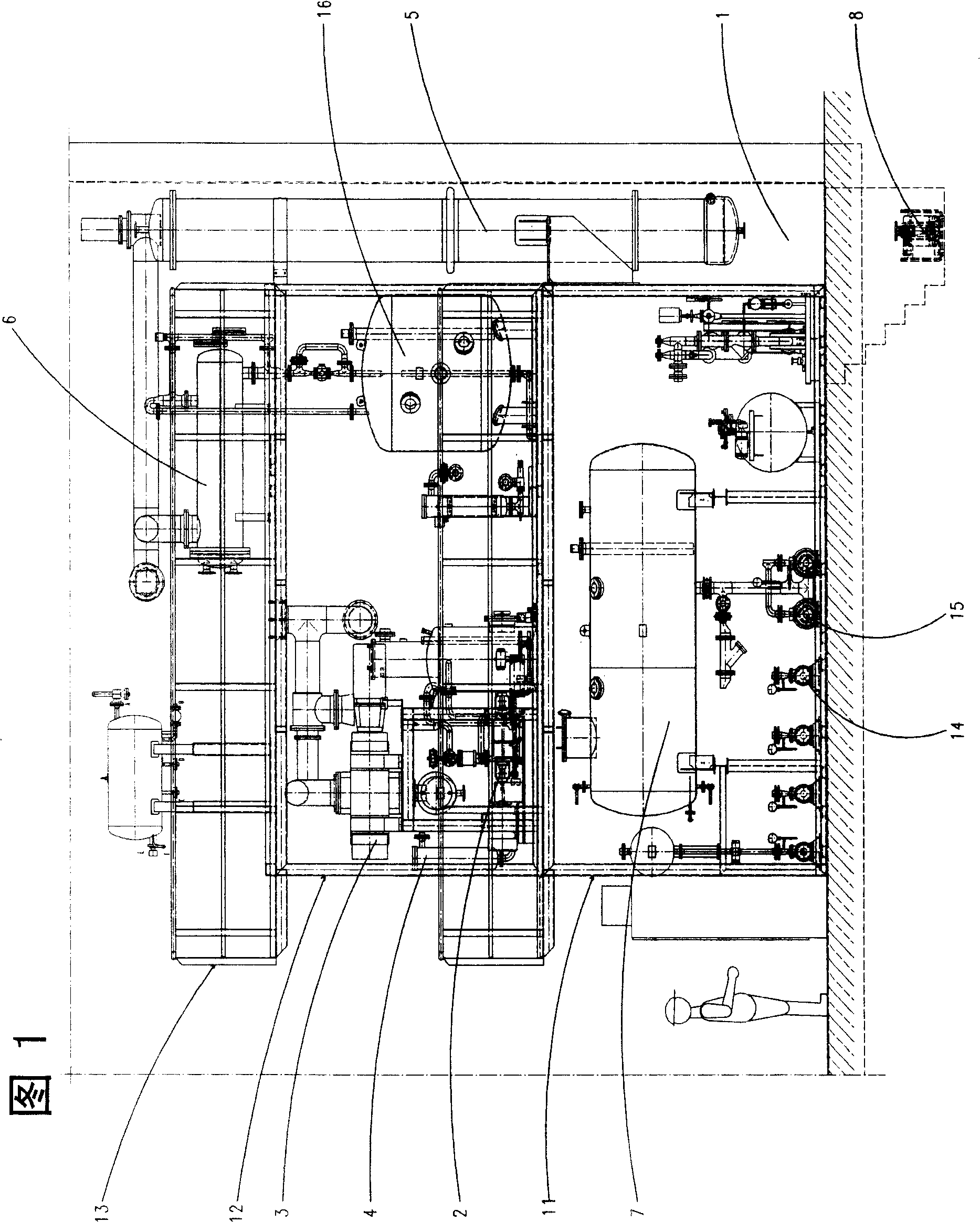
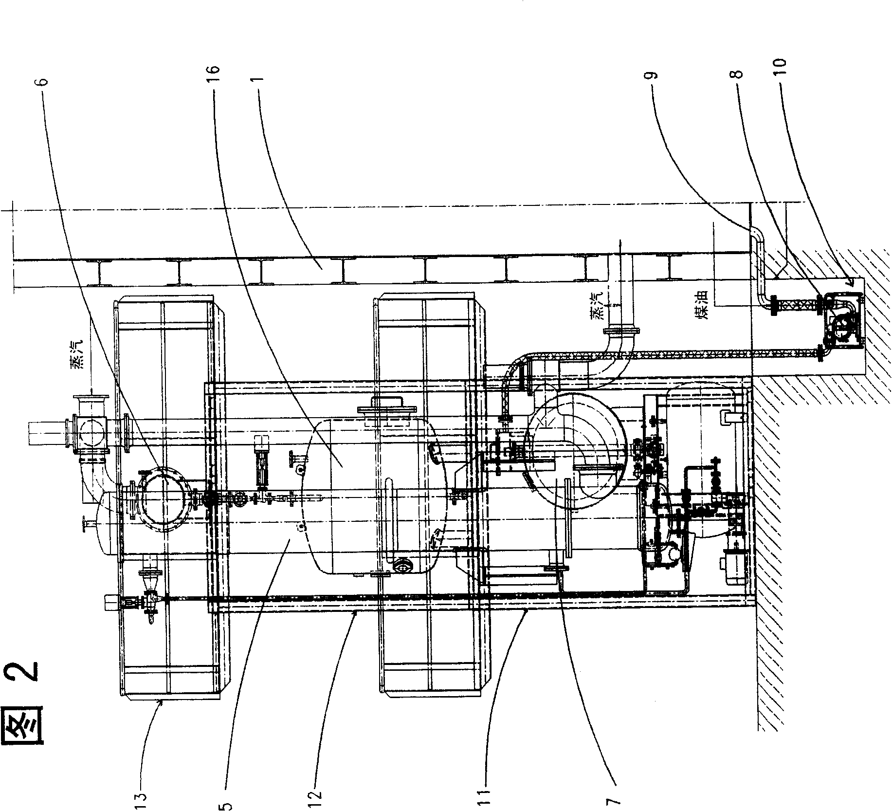
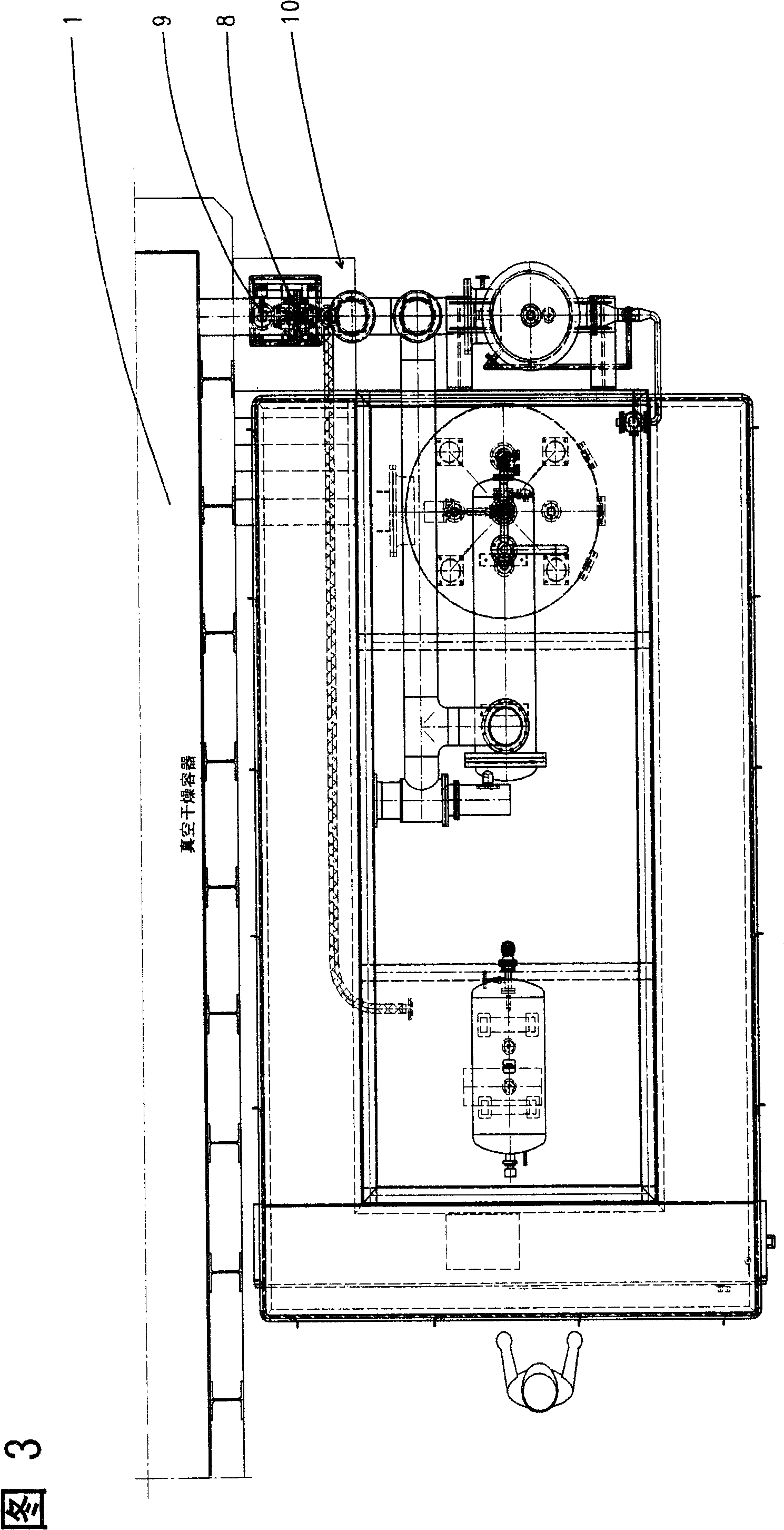
[0029] These figures show a so-called vapor phase plant, which is used, for example, for heating and drying components with hygroscopic electrical insulation parts based on cellulose and / or plastic, especially for transformers, capacitors and the like.

[0030] The basic structure of such a device and its mode of operation are described, for example, in DE 196 37 313 C2.

[0031] According to this document, the device has an evacuable vacuum chamber 1 in which transformers to be dried are inserted.

[0032] An evaporator for evaporating the heat transfer liquid is connected to the vacuum chamber 1 via a shut-off valve (not shown separately). A bypass line, which can also be closed via a valve, leads to a condenser 6 . The possibility of draining the second liquid with a higher boiling point, in particular transformer oil, is to lead via a (not shown) valve to the delivery pump 14 or via a (not shown) valve to a collecting container 7 , Through this collecting vessel, the con...


PUM


Abstract

The invention relates to a device for heating and drying wet-adsorption insulated element as transformer, via the condensed energy of steam of carrier liquid, wherein in heating period, the second liquid with high boiling point and the carrier liquid form one solution; said device comprises: a vacuum room (1) which can be vacuumed; several vacuum devices (2, 4); at least one vaporizer (5) used in carrier liquid; at least one condenser for condensing the steam of carrier liquid and the discharged wet air; and one collecting container (7) connected with said vacuum room; said collecting container is at the same height of vacuum room; and one pump (8) is between the vacuum room and the collecting container, while the input part (9) of pump is under the vacuum room.

Description

technical field [0001] The invention relates to a device for heating in vacuum a component having a hygroscopic electrically insulating part based on cellulose and / or plastic for drying purposes. Background technique [0002] Various methods are known according to which the part to be dried in a vacuum is heated to the desired temperature. What the present invention relates to is condensation heating method, generally called vapor phase method (Vapour-Phase-Verfahren). [0003] Such a method or a corresponding device is known from DE 44 46 204 C1 or DE 196 37 313 . Therein, the components to be dried—essentially paper-insulated electrical components such as transformers, capacitors, current transformers or electrical insulating bushings—are conveyed into a vacuum-tight chamber or an autoclave. Before the paper insulation is impregnated with transformer oil to increase its dielectric strength, it is necessary to extract from the paper the water that has penetrated into the ...

Claims


Application Information

Patent Timeline
Patent Type & Authority Patents(China)
IPC IPC(8): F26B5/04F26B21/14H01B19/02
CPCF26B5/04B01D5/009H01B19/02F26B21/145F26B25/006B01D5/006B01D5/0081
Inventor 库尔特·孔茨维尔纳·维尔茨赫尔穆特·施特萨拉
Owner WILHELM HENDRICH VAKUUMANLAGEN & K G
Why Eureka
Try Eureka