Combined operating switch device

A composite operation and switching device technology, which is applied in the direction of electric switches, electrical components, circuits, etc., can solve the problems of flux infiltration into the interior, etc., and achieve the effect of improving operability and improving work reliability

Active Publication Date: 2008-11-26
MITSUMI ELECTRIC CO LTD
View PDF3 Cites 0 Cited by
  • Summary
  • Abstract
  • Description
  • Claims
  • Application Information

AI Technical Summary

Problems solved by technology

Therefore, when the multi-operation type switch device is mounted on the base by reflow soldering, there is a problem that the flux will penetrate into the inside from the hole in the base and the gap in the shaft.

Method used


Image

  • Combined operating switch device
  • Combined operating switch device
  • Combined operating switch device

Examples


Embodiment Construction

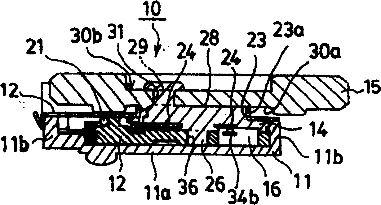
[0042] In order to achieve a structure in which flux does not infiltrate into the inside of the switchgear even when mounting on a substrate using a reflow soldering method, the present invention adopts a structure in which the base of the plate is covered with a cover plate On the upper part, a storage part with a closed bottom surface and a side surface is formed, and the switch components are arranged in the storage part. When this structure is adopted, even if the reflowed solder touches the underside of the bottom of the base during reflow soldering, since the bottom of the base is closed, the flux will not infiltrate into the housing from the bottom. Ministry. Thus, a multi-operation type switchgear that can be mounted using the reflow soldering method is obtained.

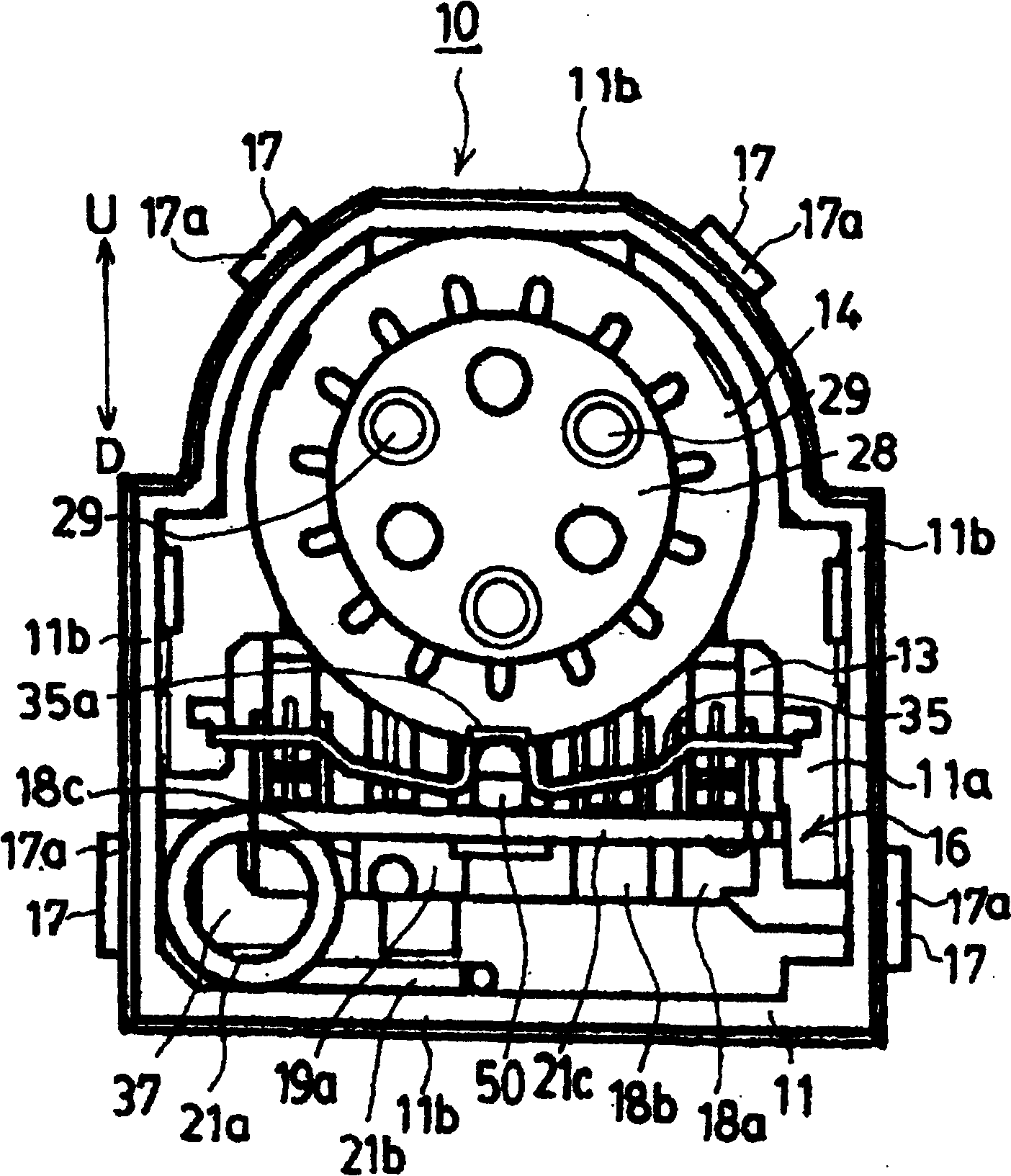
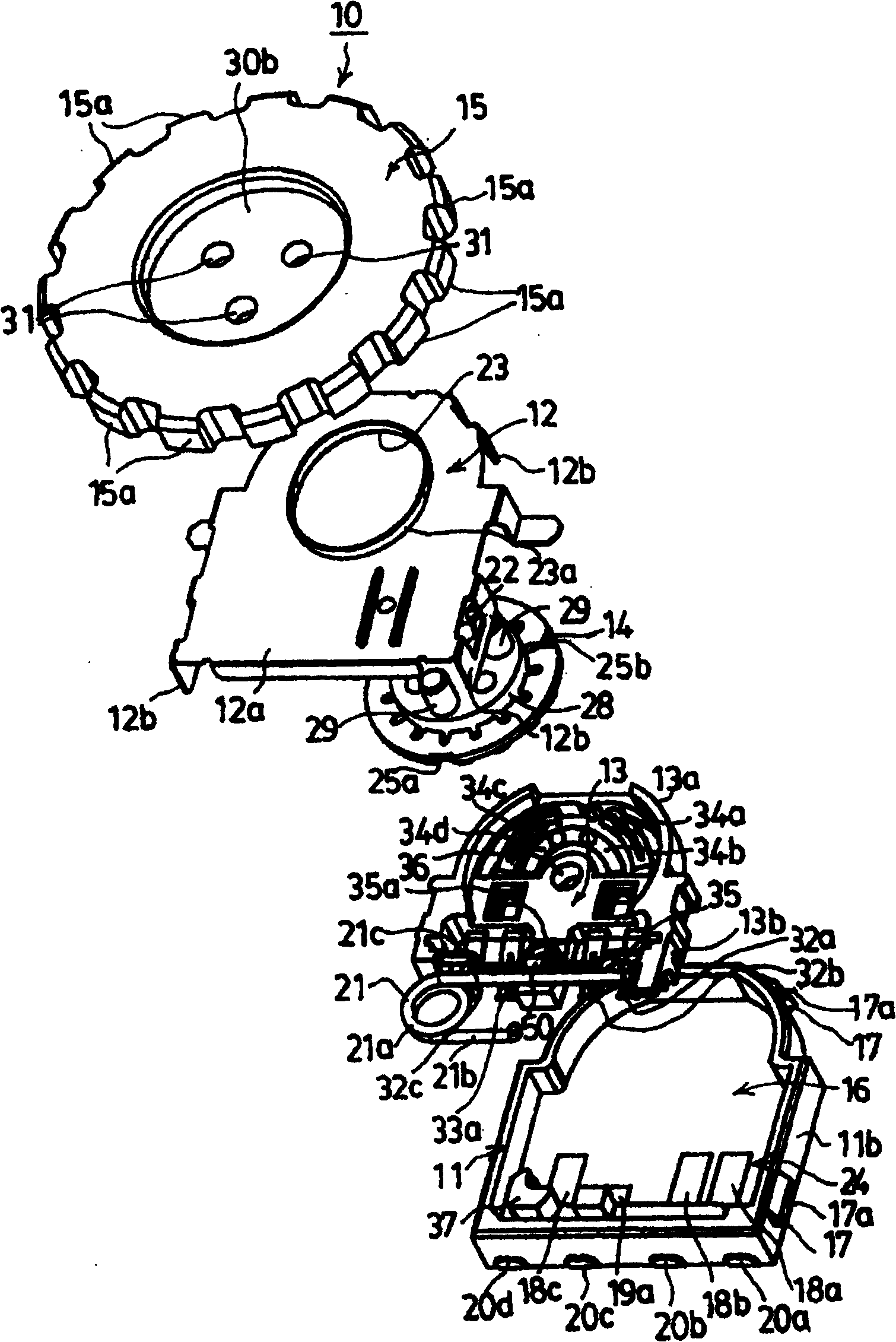
[0043] Figure 1 to Figure 7 Represents the embodiment of the composite operation type switchgear of the present invention, figure 1 is a longitudinal sectional view of the composite operation type switch...


PUM


Abstract

To obtain a structure wherein no flux penetrates into a switching arrangement, when mounting it to a substrate by using a reflow-soldering method. In the structure of this combined operation type switching arrangement, a housing part 16 is formed with its bottom face and sides closed on a base 11 the top face of which is covered with a cover 12, and a switch constituting element is disposed in the housing part 16. By this structure, when reflow-soldering is applied to the combined operation type switching arrangement, no flux penetrates into the housing 16 from the bottom face 11 side, because the bottom face side of the base 11 is closed. Thereby, the combined operation type switching arrangement mountable by using the reflow-soldering method can be obtained.

Description

technical field [0001] The present invention relates to a multi-operation switch device, and more particularly, to a multi-operation type switch device in which individual switches are actuated by a plurality of different operations of a rotary operation and a push operation of a dial member operated by a user. Background technique [0002] Generally, in order for a multi-operation type switch device used as an input device in electronic devices such as video cameras, digital cameras, and mobile phones to perform predetermined processing, it is required to operate several switches smoothly and continuously. Therefore, the input unit in these electronic devices can individually operate several switches by the user operating only one operation unit (for example, refer to Patent Document 1 - Japanese Patent Application Laid-Open No. 9-63420). [0003] The composite operation switch device of Patent Document 1 is adopted, and the composite operation switch device has: a turntabl...

Claims


Application Information

Patent Timeline
Patent Type & Authority Patents(China)
IPC IPC(8): H01H25/00
Inventor 河村乔
Owner MITSUMI ELECTRIC CO LTD
Why Eureka
Try Eureka