
Air bag device

An airbag and air chamber technology, applied in transportation and packaging, pedestrian/passenger safety arrangement, vehicle safety arrangement, etc., can solve the problems of airbag delay, hitting passengers, and failure to ensure the connection part, etc.

Inactive Publication Date: 2008-12-10
ASHIMORI INDS
View PDF6 Cites 0 Cited by
  • Summary
  • Abstract
  • Description
  • Claims
  • Application Information

AI Technical Summary

Problems solved by technology

[0009] However, this airbag device has the following problems, that is, it is necessary to separately manufacture a check valve and fix it on a partition wall of a size that can be mounted, and the number of parts increases, and it is impossible to secure a communication portion when the shape of the air passage is required to be small.
[0010] In this conventional airbag, since the upper chamber is simply formed in a bag shape, the gas from the inflator diffuses to the entire upper chamber when the airbag is inflated. A large amount of gas flows into the upper gas chamber in a short time
In addition, if the gap between the passenger and the door trim or the side wall is too narrow, when the airbag is inflated, not only the gas flow from the passenger's chest (or waist) to the head will be restricted, causing the airbag to expand toward the head. is delayed, and the pressure rise caused by the constriction of the gas flow can cause partial damage to the airbag or there is a risk of localized direct impact on the occupant

Method used


Image

  • Air bag device
  • Air bag device
  • Air bag device

Examples


Embodiment Construction

[0045] Next, an airbag device for a side collision according to an embodiment of the airbag device according to the present invention will be described with reference to the drawings.

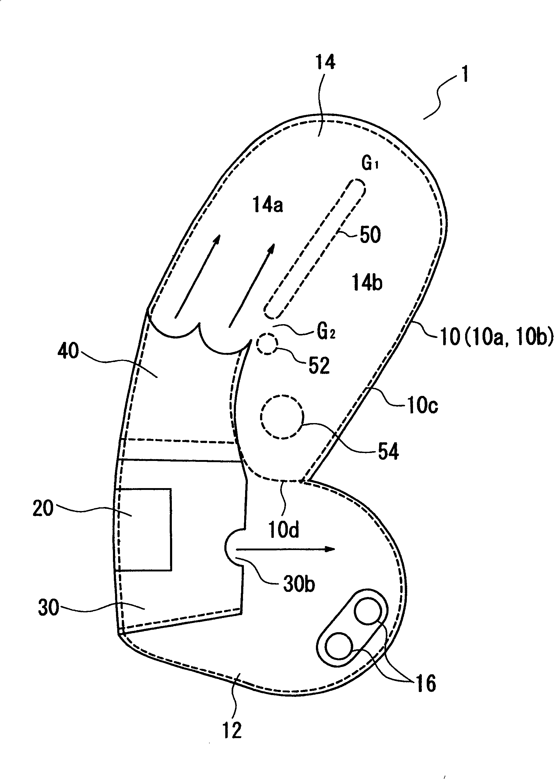
[0046] figure 1 It is a schematic sectional view for explaining the overall structure of one embodiment of the airbag device of the present invention.

[0047] As shown in the figure, the airbag 10 of the airbag device 1 for side collision is made of synthetic fiber fabrics such as polyamide and polyester which are generally used for airbags and which have been coated with resin. 10b and 10b are formed by sewing together with sewing thread 10c along the entire peripheral portion thereof. And, using the sewing thread 10d branched from the sewing thread 10c that sews the base fabrics 10a and 10b on the front side and the back side, the lower part of the chest (or waist) protection as the first air chamber extending laterally is The air chamber 12 is divided into an upper air chamber 14, which i...


PUM


Abstract

PROBLEM TO BE SOLVED: To smoothly deploy an airbag in even a narrow space by performing the regulation of thickness of the airbag and a conduction control of expansion gas, and to quickly and surely protect the head part of an occupant by comparatively small amount of gas. SOLUTION: This device is provided with a first air chamber 12 for protecting a breast part, a second air chamber 14 for protecting the head part, and a diffuser 30 interposed between the air chambers 12 and 14 to rectify gas jetted from an inflator 20. In the second air chamber 14, a first tether 50 to form a gas conducting passage 14a for guiding gas blown from a blowoff port of the diffuser 30 to penetrate from a rear side of the head part protecting region of the airbag 1 to a front side is provided. At a lower end of the first tether 50 in the vicinity of the gas blowoff port, a second tether 52 for forming a gap to release a part of gas to a front part of the second air chamber 14 is provided in a space between the first tether 50.

Description

technical field [0001] The present invention relates to an airbag device having an airbag having an inflator, a first air chamber for waist or chest protection, and a second air chamber for head protection into which the gas of the inflator is introduced from the first air chamber. In particular, it relates to an airbag device that can be easily deployed in a limited space and that can easily introduce gas into a head guard in a second air chamber. Background technique [0002] Airbags are generally used to protect passengers in a side collision in which the waist of the passenger sitting on the seat first hits the door and receives an impact, and then the chest of the passenger collides with the door. [0003] However, conventional airbag devices for side impact countermeasures use a structure in which one airbag is uniformly inflated as a whole. However, if it is desired to sufficiently absorb energy during a side collision with this structure, this structure is not ideal ...

Claims


Application Information

Patent Timeline
Patent Type & Authority Patents(China)
IPC IPC(8): B60R21/231B60R21/26B60R21/16B60R21/207B60R21/2338B60R21/2346
Inventor 田口征吾石龟胜义菅原勉山路直树东英孝
Owner ASHIMORI INDS
Learn More