Adhesive chuck device

A chuck and substrate technology, used in identification devices, nonlinear optics, instruments, etc., can solve problems such as increased manufacturing cost, high failure rate, glass plate damage, etc., to avoid the danger of influence or discharge, and the failure rate. Reduced, Safe and Correctly Aligned Effects

Inactive Publication Date: 2008-12-31
SHIN ETSU ENG
View PDF10 Cites 0 Cited by
  • Summary
  • Abstract
  • Description
  • Claims
  • Application Information

AI Technical Summary

Problems solved by technology

[0012] However, in such a conventional adhesive chuck device, in the case of Patent Document 1, there is a problem that in order to peel off the adhesive member and the substrate, the adhesive sheet must be rolled up and pressed against the roll. The speed is synchronized with the speed so that it moves horizontally in the same winding direction, or the tool table and the tool base must be raised to pass the tool to cut the adhesive sheet. Each action requires multiple driving sources such as motors or actuators, resulting in structural complication
[0013] Furthermore, in the case of Patent Document 2, in order to raise the bonding member in the opening of the pressure plate, a plurality of actuators are required for each bonding member, while in the case of Patent Document 3, each Each bonding member requires a rotation actuator and an actuator for driving up and down to move the bonding member back while rotating, respectively, resulting in a complicated structure.
[0014] Therefore, Patent Documents 1 to 3 not only have a high incidence of failure due to the complicated peeling structure, but also have the following problems, that is, especially when they are arranged in a substrate assembly device or a substrate transfer device including a substrate bonding machine, etc. , it is difficult to replace the original electrostatic chuck and other substrate holding mechanisms with the bonding chuck device of the present invention
[0015] Moreover, there is a problem that when the above-mentioned actuator is an electromagnetic motor such as a motor, it will easily generate heat. For example, a substrate made of glass is sensitive to thermal changes, and it will shrink by about 4 μmm with only a change of 1°C. Due to this effect, it is difficult to align the substrates correctly with respect to each other
[0016] And there is also the following problem, that is, when the adhesive is held in an ambient gas from atmospheric pressure to a predetermined degree of vacuum, and when the adhesion is peeled off and opened, the change from atmospheric pressure to a predetermined degree of vacuum, but if the motor is used If there is an electromagnetic actuator in the vacuum, at some point in the vacuum there may be a plasma discharge, which will lead to the destruction of the glass plate
[0017] Moreover, there is a problem that, even if the above-mentioned actuator is a driving source such as a cylinder, it is difficult to downsize because it has a sealed structure that can operate telescopically, so that the entire device becomes large and causes an increase in manufacturing cost.
[0018] However, especially large-scale substrates are prone to distortion and deformation. In order to firmly bond and hold such easily deformable substrates and open and peel them off, it is necessary to use a strong force to make the bonding parts contact or separate the substrates. In order to obtain such a strong force The actuator must be upsized, resulting in a heavier weight

Method used


Image

  • Adhesive chuck device
  • Adhesive chuck device
  • Adhesive chuck device

Examples


Embodiment 1

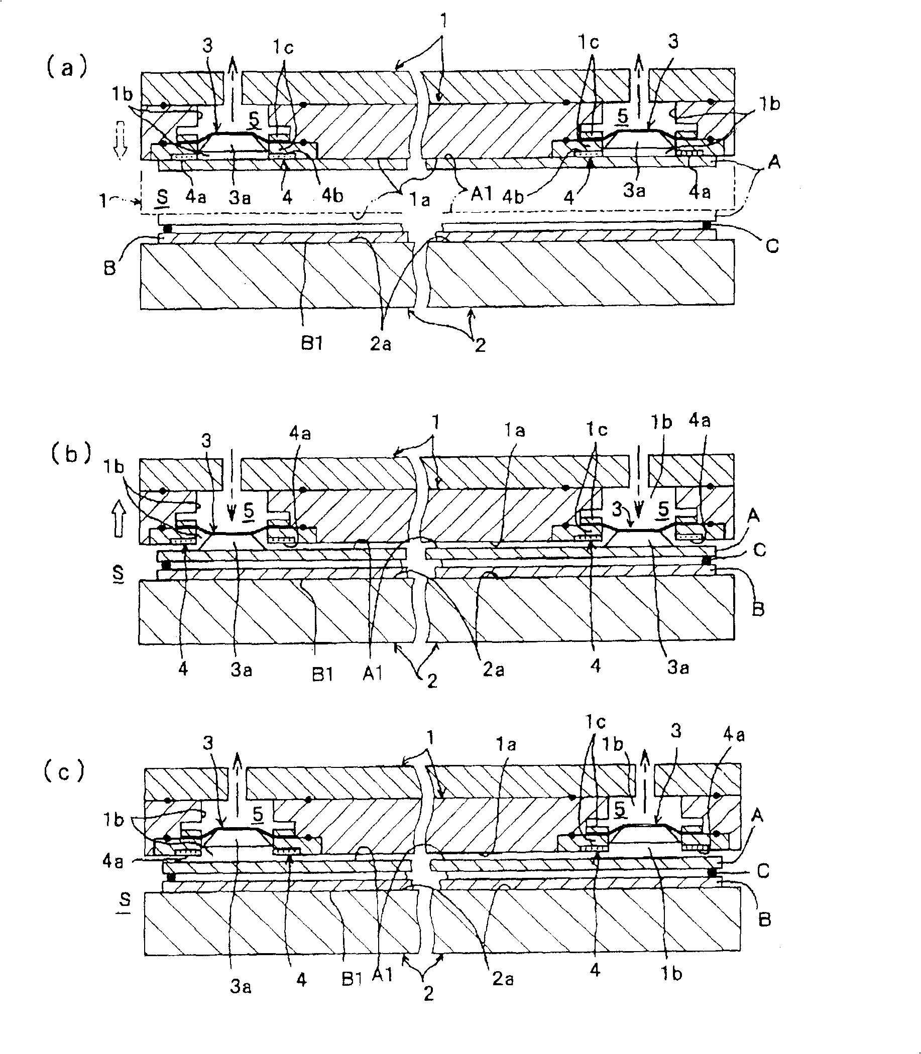
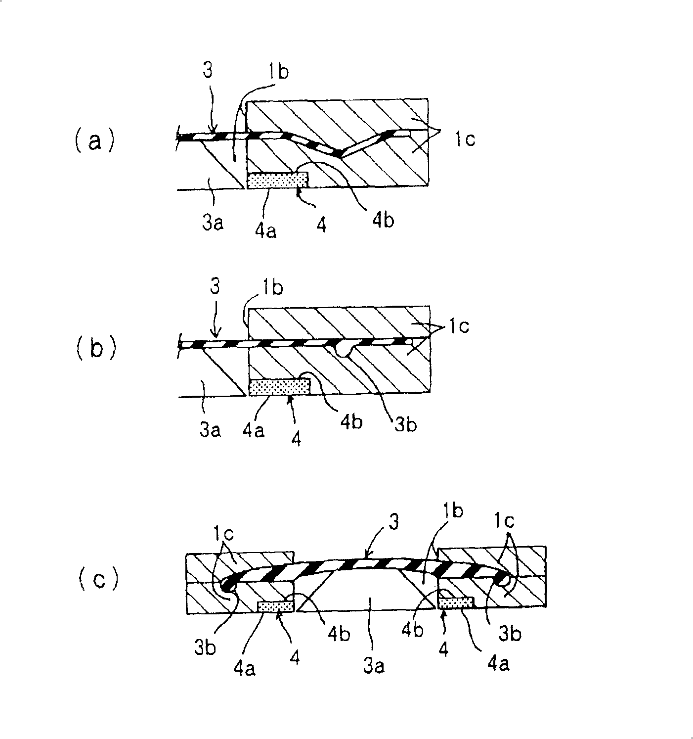
[0112] The embodiment 1 as figure 1 As shown in (a) to (c), the following cases are shown, that is, a plurality of openings 1b are opened only on the holding surface 1a of the upper holding plate 1, and the outer peripheral portion of the movable film 3 is supported. Part of the rigid body portion 3a is provided facing the surface A1 of the substrate A, and at the same time, the ring-shaped adhesive member 4 is fixed along the opening edge of each opening portion 1b located on the secondary side of the movable film 3, and the rigid body portion 3a is attached to the rigid body portion. In the state where the part 3a moves upward and enters the opening part 1b, the bonding member 4 is brought into contact with the upper substrate A and bonded and held. The underside protrudes and deforms, and the substrate A bonded and held on the bonding surface 4a of the bonding member 4 is forcibly peeled off.

[0113] In addition, in the illustrated example, due to the spatial relationshi...

Embodiment 2

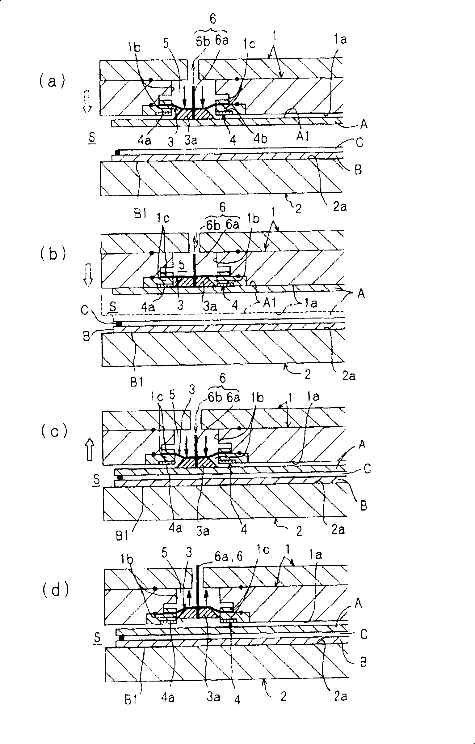
[0140] The embodiment 2 as image 3 As shown in (a) to (d), there is provided an air passage 6a penetrating in the reciprocating direction of the movable film 3, and a gas supply source 6b for supplying gas such as nitrogen gas by vacuum suction from the air passage 6a. When the upper substrate A is installed, the vacuum suction mechanism 6 performs vacuum suction from the air channel 6a of the vacuum adsorption mechanism 6 to absorb and hold the upper substrate A, and then when peeling off from the adhesive member 4 as required, upwards from the air channel 6a. The surface A1 of the substrate A ejects gases such as nitrogen, and this structure is the same as the above-mentioned Figure 1 ~ Figure 2 The illustrated embodiment 1 is different, and the other configurations are the same as those of the first embodiment.

[0141] In the illustrated example, an air passage 6a is perforated so as to pass through the movable membrane 3 and the rigid body part 3a provided on a part th...

Embodiment 3

[0150] The embodiment 3 as Figure 4 As shown in (a) to (c), the fixing position of the above-mentioned bonding member 4 is not provided on the opening edge of the opening 1b, but is changed and provided on the rigid body part 3a protruding from the central part of the movable membrane 3. At the same time, through the pressure difference between the primary side space (pneumatic chamber) 5 and the secondary side space (closed space) S of the movable membrane 3, on the bonding surface 4a of the bonding member 4 and the holding surface 1a The upper substrate A is brought into contact with the bonding surface 4a of the bonding member 4 to be bonded and held in a substantially flat or slightly (about 100 μm) convex state, and the movable film 3 is directed toward the primary side The space (pneumatic chamber) 5 deforms upward to enter the opening 1b in a concave shape, thereby forcibly peeling the bonding surface 4a of the bonding member 4 from the upper substrate A. This structur...


PUM


Abstract

A bonding chuck device that securely loads and unloads substrates with a simple-structured pneumatic mechanism. A movable film (3) and an adhesive member (4) are provided on the substrate side of the holding plate (1), and the movable film (3) can be opened in the opening (1b) on the side surface (1a) of the substrate. Deformed in a direction intersecting with the side surface (1a) of the substrate, the adhesive structure member (4) is bonded and held opposite to the substrate (A), and passes through the primary side space (5) and secondary side space (5) of the movable membrane (3) The pressure difference in the space (S) causes the movable film (3) to reciprocate, so that the adhesive surface (4a) of the adhesive member (4) and the substrate (A) are abutted to be bonded and maintained, and at the same time, the film is pulled apart by force. Both, the substrate (A) can be easily peeled off from the bonding surface (4a) of the bonding member (4).

Description

technical field [0001] The present invention relates to an adhesive chuck device used in a substrate assembly device including a substrate bonding machine used in, for example, a liquid crystal display (LCD) or a plasma display (PDP), etc. In the manufacturing process of flat panel displays, glass substrates such as CF glass and TFT glass or synthetic resin substrates are bonded and held together. [0002] In detail, it relates to a bonding chuck device for detachably holding a substrate by bonding to a holding plate. Background technique [0003] Conventionally, in a substrate bonding machine that overlaps two substrates, the substrate is held by an electrostatic chuck. However, with the increase in the size of the substrate in recent years, it is difficult to manufacture a large-sized electrostatic chuck, and even if it can be manufactured, the cost It will also be very high. [0004] Then, in order to solve these problems, there is an adhesive chuck device that uses an ...

Claims


Application Information

Patent Timeline
Patent Type & Authority Patents(China)
IPC IPC(8): G02F1/1333G09F9/00
CPCG02F1/1333G02F1/13
Inventor 横田道也大谷义和板下光邦
Owner SHIN ETSU ENG
Why Eureka
Try Eureka