Adhesive chuck device
A technology for chucks and substrates, applied in identification devices, nonlinear optics, optics, etc., can solve problems such as increased manufacturing costs, high failure rates, glass plate damage, etc., to avoid the risk of impact or discharge, and the failure rate Lowered, safe and correct alignment effect
- Summary
- Abstract
- Description
- Claims
- Application Information
AI Technical Summary
Problems solved by technology
Method used
Image
Examples
Embodiment 1
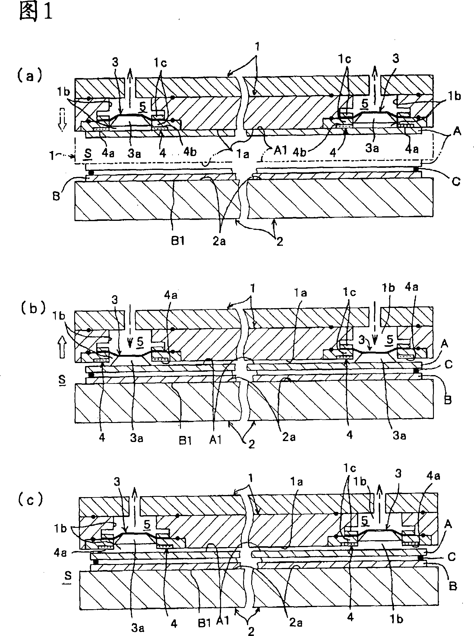
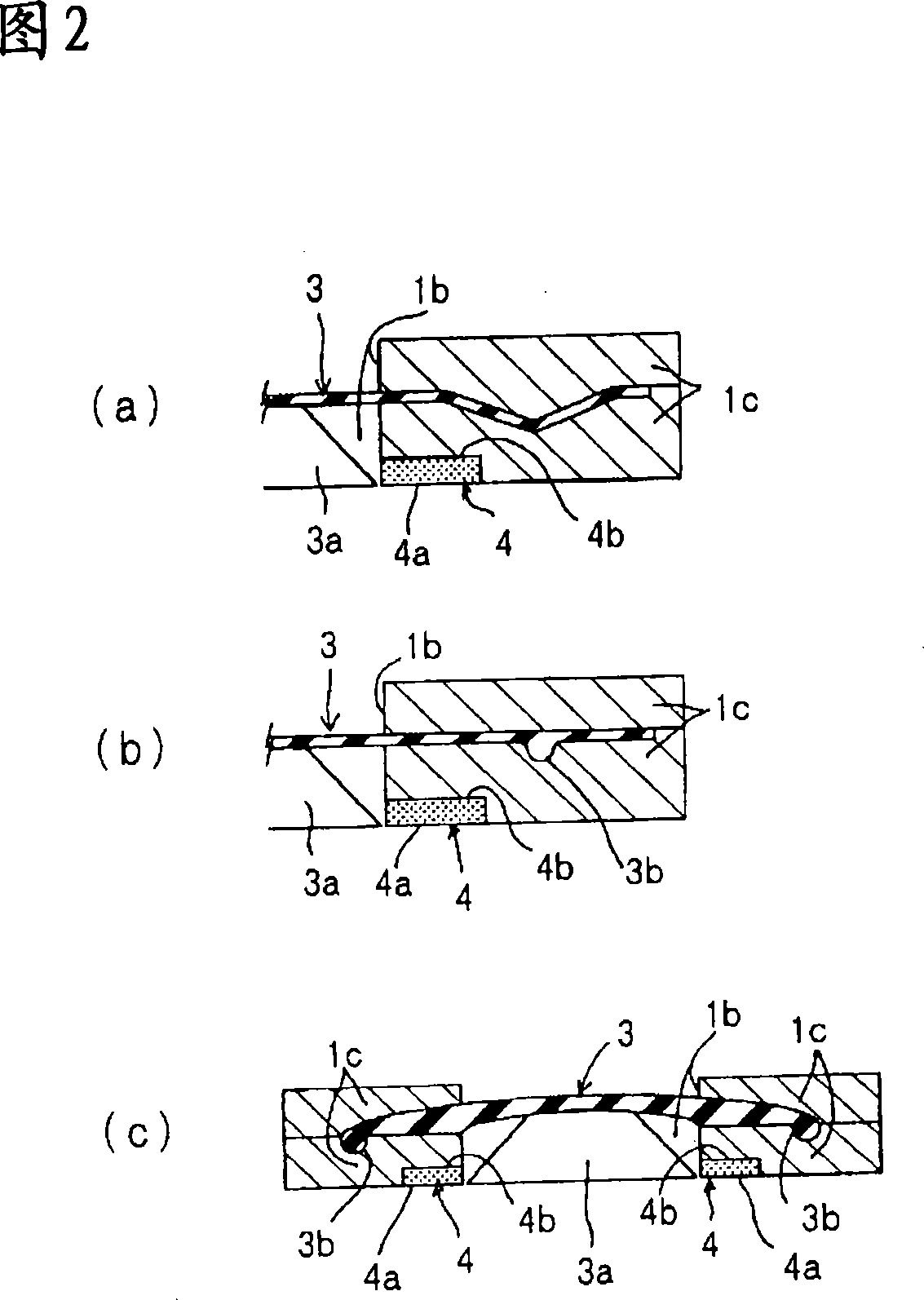
[0112] In this first embodiment, as shown in FIGS. 1( a ) to ( c ), a plurality of openings 1 b are opened only in the holding surface 1 a of the upper holding plate 1 to support the outer peripheral portion of the movable film 3 . A rigid portion 3a is provided on a part of the movable membrane 3 facing the surface A1 of the substrate A, and a ring-shaped adhesive is fixed along the opening edge of each opening 1b located on the secondary side of the movable membrane 3. In the state where the rigid body part 3a moves upward and enters the opening part 1b, the bonding member 4 is brought into contact with the upper substrate A and bonded and held, and the movable film 3 is directed toward the secondary side. The space (closed space) S protrudes and deforms downward, and the substrate A bonded and held on the bonding surface 4 a of the bonding member 4 is forcibly peeled off.
[0113] In addition, in the illustrated example, due to the spatial relationship, only two openings 1b...
Embodiment 2
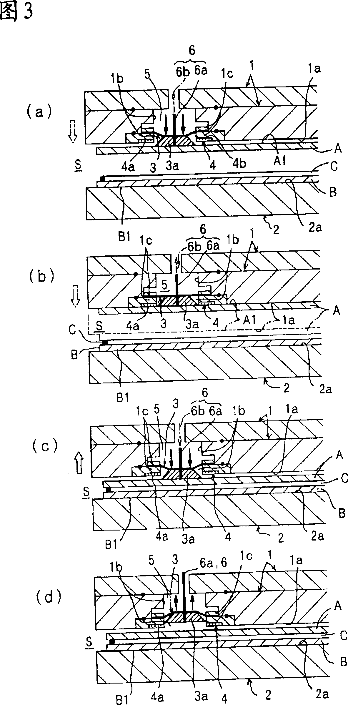
[0140] This embodiment 2, as shown in Fig. 3 (a) ~ (d), is provided with the air channel 6a that penetrates along the reciprocating motion direction of the above-mentioned movable film 3, and vacuum suction is performed from the air channel 6a and supply, for example, nitrogen gas etc. When the vacuum adsorption mechanism 6 constituted by the gas supply source 6b is mounted on the upper substrate A, the upper substrate A is sucked and held by vacuum suction through the air passage 6a of the vacuum adsorption mechanism 6, and then peeled off from the adhesive member 4 as required. For example, gas such as nitrogen is sprayed from the air channel 6a to the surface A1 of the upper substrate A. This structure is different from the first embodiment shown in FIGS.
[0141]In the illustrated example, an air passage 6a is perforated so as to pass through the movable membrane 3 and the rigid body part 3a provided on a part thereof in the vertical direction. The penetrating position of ...
Embodiment 3
[0150] In this embodiment 3, as shown in Fig. 4 (a) to (c), the fixing position of the above-mentioned bonding member 4 is not set at the opening edge of the opening 1b, but is changed and set at the protruding position of the movable film. 3. At the front end surface of the rigid body part 3a at the central part, at the same time, the pressure difference between the primary side space (pneumatic chamber) 5 and the secondary side space (closed space) S of the movable membrane 3 is applied to the bonding member 4. In a state where the bonding surface 4a and the holding surface 1a are substantially in the same plane or slightly (about 100 μm) protruding, the upper substrate A is brought into contact with the bonding surface 4a of the bonding member 4 to bond and hold it. The movable membrane 3 deforms upward toward the primary-side space (pneumatic chamber) 5 and enters the opening 1b in a concave shape, thereby forcibly peeling the adhesive surface 4a of the adhesive member 4 fr...
PUM
 Abstract
Description
Claims
Application Information
 - R&D
- Intellectual Property
- Life Sciences
- Materials
- Tech Scout
- Unparalleled Data Quality
- Higher Quality Content
- 60% Fewer Hallucinations
Browse by: Latest US Patents, China's latest patents, Technical Efficacy Thesaurus, Application Domain, Technology Topic, Popular Technical Reports.
© 2025 PatSnap. All rights reserved.Legal|Privacy policy|Modern Slavery Act Transparency Statement|Sitemap|About US| Contact US: help@patsnap.com


