
Coupling type clutch

A clutch and coupling technology, applied in the direction of belt/chain/gear, mechanical equipment, transmission device, etc., can solve the problems of single function, complex structure, high processing precision requirements and high cost, and achieve wide application, simple basic structure, The effect of combining high efficiency

Inactive Publication Date: 2009-01-14
吴学新
View PDF9 Cites 0 Cited by
  • Summary
  • Abstract
  • Description
  • Claims
  • Application Information

AI Technical Summary

Problems solved by technology

[0008] The purpose of the present invention is to provide a coupling clutch with better performance, more functions and wider application in view of the disadvantages of the existing coupling clutches, such as relatively complex structure, single function, high requirements on machining accuracy and high cost.

Method used


Image

  • Coupling type clutch
  • Coupling type clutch
  • Coupling type clutch

Examples


Embodiment Construction

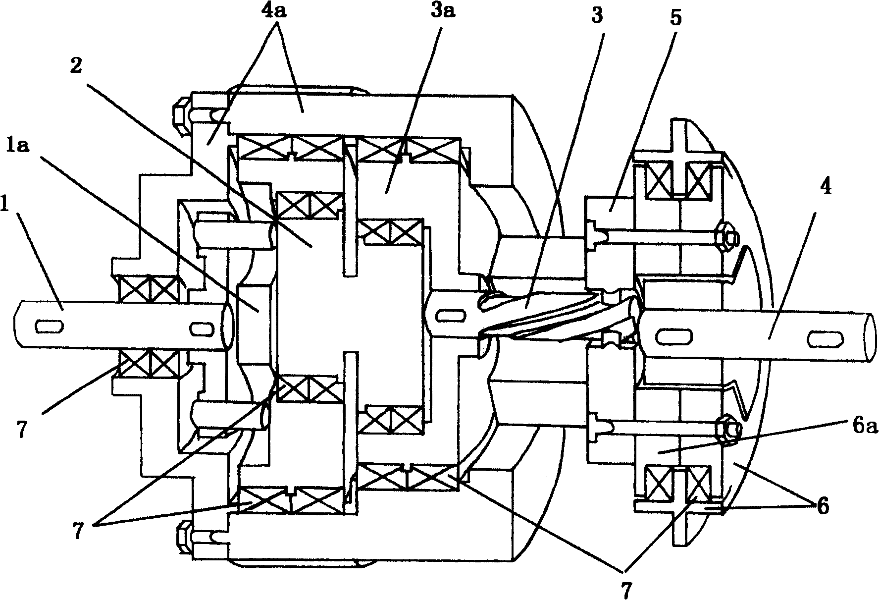
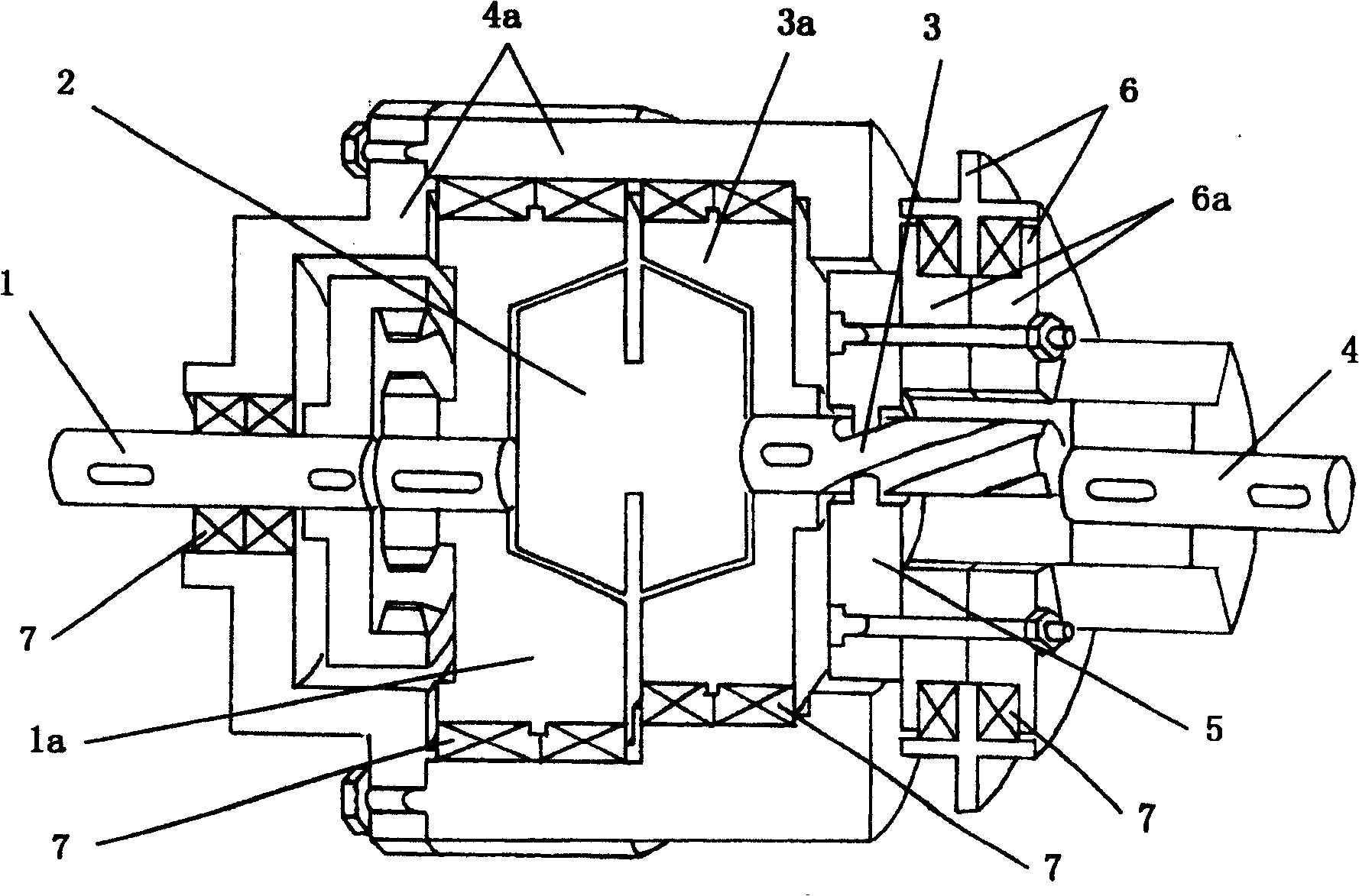
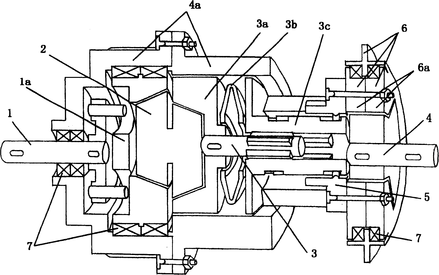
[0036] see Figure 1~5 , the present invention is provided with first transmission shaft 1, wheel disc 1a, eccentric wheel 2, self-aligning shaft 3, self-aligning wheel disc 3a, spring 3b, spiral bushing 3c, second transmission shaft 4, transmission case 4a, pin Gear 5, clutch control disc 6 (the inner sleeve 6a of clutch control disc is provided therein), bearing 7 and so on.

[0037] The first transmission shaft 1 and the wheel disc 1a are gear meshingly connected, and may also be connected by fixed connection, constant speed or differential mechanism (such as being connected by a gear train or a constant speed output mechanism), and the first transmission shaft 1 and the wheel disc 1a pass through The bearing 7 is connected with the transmission housing 4a and the left end of the eccentric wheel 2 respectively. The self-aligning shaft 3 is fixedly connected with the self-aligning wheel 3a, and the self-aligning wheel 3a is respectively connected to the right end of the ecc...


PUM


Abstract

The present invention relates to a coupled clutch, belonging to one kind of drive device. Said coupled clutch includes the following several portions: first drive shaft, wheel disk, eccentric wheel, aligning wheel disk, aligning shaft, drive shell body, pin gear, clutch control disk, second drive shaft, bearing and screw bolt. Besides, said invention also provides their connection mode.

Description

technical field [0001] The invention relates to a transmission device, in particular to a coupling clutch. Background technique [0002] Clutch is a shafting part in a commonly used mechanical transmission device. It is often used to separate or engage the power connection between power devices. It can also be used for starting, parking, reversing, speed change, orientation and overload protection. Its products There are many kinds, and most of them are standardized. Clutches can be divided into manipulative clutches and self-control clutches according to the way of clutch action, among which manipulative clutches can be divided into mechanical manipulative clutches, electromagnetic manipulative clutches, pneumatic manipulative clutches and hydraulic manipulative clutches, etc. Self-manual clutches can be divided into overrunning clutches and centrifugal clutches. and safety clutch etc. [0003] BorgWarner provides a fluid friction clutch especially for fans of internal co...

Claims


Application Information

Patent Timeline
Patent Type & Authority Patents(China)
IPC IPC(8): F16H37/00
Inventor 吴学新
Owner 吴学新
Learn More