
DC arc induction furnace

A DC arc and induction furnace technology, applied in the field of induction furnaces, can solve problems such as increased production cost, longer smelting time, and reduced furnace age, and achieves the effect of preventing scrap steel from bridging, shortening smelting time, and ensuring the quality of molten steel

Inactive Publication Date: 2009-01-14
NORTHEASTERN UNIV LIAONING
View PDF6 Cites 0 Cited by
  • Summary
  • Abstract
  • Description
  • Claims
  • Application Information

AI Technical Summary

Problems solved by technology

Due to bridging, the smelting time is prolonged, the oxidation amount of steel is increased, the yield of products is reduced, the power consumption is high, and the production cost is increased.
In addition, due to the bridging, the operator must carry out manual ramming, which will increase the loss of the furnace lining and reduce the furnace life. Therefore, the production cost will increase, the labor intensity of the workers will increase, and the production efficiency will decrease.
Moreover, non-vacuum induction furnaces usually do not have the function of refining molten steel, and the smelted molten steel is usually of low cleanliness and poor product quality
DC electric arc furnace is usually used to melt scrap steel and (or) to refine molten steel. Its disadvantages are low stirring intensity of molten pool, poor metallurgical reaction kinetics conditions, and high non-metallic inclusions in steel.

Method used


Image

  • DC arc induction furnace

Examples


Embodiment Construction

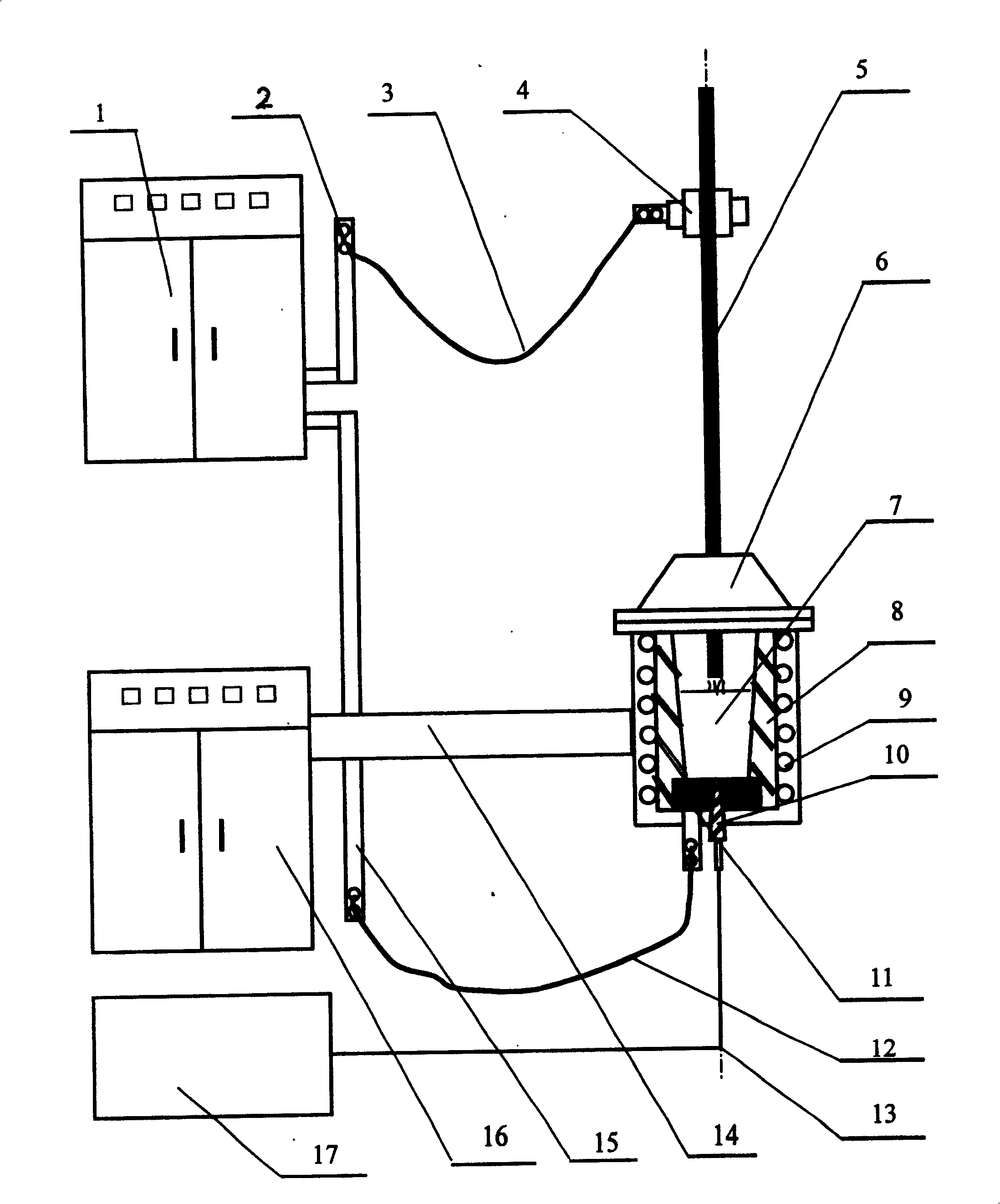
[0009] As shown in the drawings, the DC arc induction furnace of the present invention includes a rectifier cabinet 1, a top cathode copper bar 2, a top cathode water-cooled cable 3, a holder 4, a top cathode 5, a furnace cap 6, a crucible 8, an induction coil 9, Bottom anode conductive brick 10, bottom blowing vent plug 11, bottom gas pipe 12, intermediate frequency conductive copper bar and water-cooled cable 13, bottom anode water-cooled cable 14, bottom anode copper bar 15, intermediate frequency power supply cabinet 16. An induction coil 9 is arranged on the outer wall of the crucible 8 of the DC arc induction furnace, and the induction coil 9 is connected to the power supply of the intermediate frequency power supply cabinet 16 through an intermediate frequency conductive copper bar and a water-cooled cable 13, and can inductively heat the charge in the crucible during smelting; at the bottom of the furnace Install furnace bottom conductive brick and high current bottom a...


PUM


Abstract

A DC arc induction furnace for refining molten steel has the top graphite cathode connected to the cathodic copper bus of rectifier chest via the water-cooled cable and the electrically conductive bottom bricks used as bottom anode connected to the anodic copper bus of rectifier chest via the water-cooled cable. Its advantages are high volume and heat capacity, long service life and high quality of molten steel.

Description

technical field [0001] The invention relates to the technical field of metallurgical equipment, in particular to an induction furnace for iron and steel smelting. Background technique [0002] The non-vacuum induction furnaces commonly used at present are generally used to melt scrap steel. Its operating process is to first add a certain amount of steel scrap (block) into the induction furnace, and then energize it for melting. Due to the different sizes and shapes of scrap steel, it is easy to cause the so-called "bridging" phenomenon. Due to bridging, the smelting time is lengthened, the oxidation amount of the steel increases, the yield of the product decreases, the power consumption is high, and the production cost increases. In addition, due to the bridging, the operator must carry out manual ramming, which will increase the loss of the furnace lining and reduce the furnace life. Therefore, the production cost will increase, the labor intensity of the workers will inc...

Claims


Application Information

Patent Timeline
Patent Type & Authority Patents(China)
IPC IPC(8): F27B3/08H05B7/06
Inventor 姜周华沙骏张天彪余强孙国会
Owner NORTHEASTERN UNIV LIAONING
Learn More