Supercharge Your Innovation With Domain-Expert AI Agents!

Method for testing a magnetic inductive flow meter

A flowmeter, magnetic induction technology, applied in the field of inspection of magnetic induction flowmeter

Inactive Publication Date: 2009-01-14
ENDRESS HAUSER FLOWTEC AG
View PDF23 Cites 0 Cited by
  • Summary
  • Abstract
  • Description
  • Claims
  • Application Information

AI Technical Summary

Problems solved by technology

Due to the eddy currents in the pole pieces and the magnetic core of the coil arrangement during the change of the magnetic field, the reality does not correspond to this ideal situation

Method used


Image

  • Method for testing a magnetic inductive flow meter
  • Method for testing a magnetic inductive flow meter
  • Method for testing a magnetic inductive flow meter

Examples


Embodiment Construction

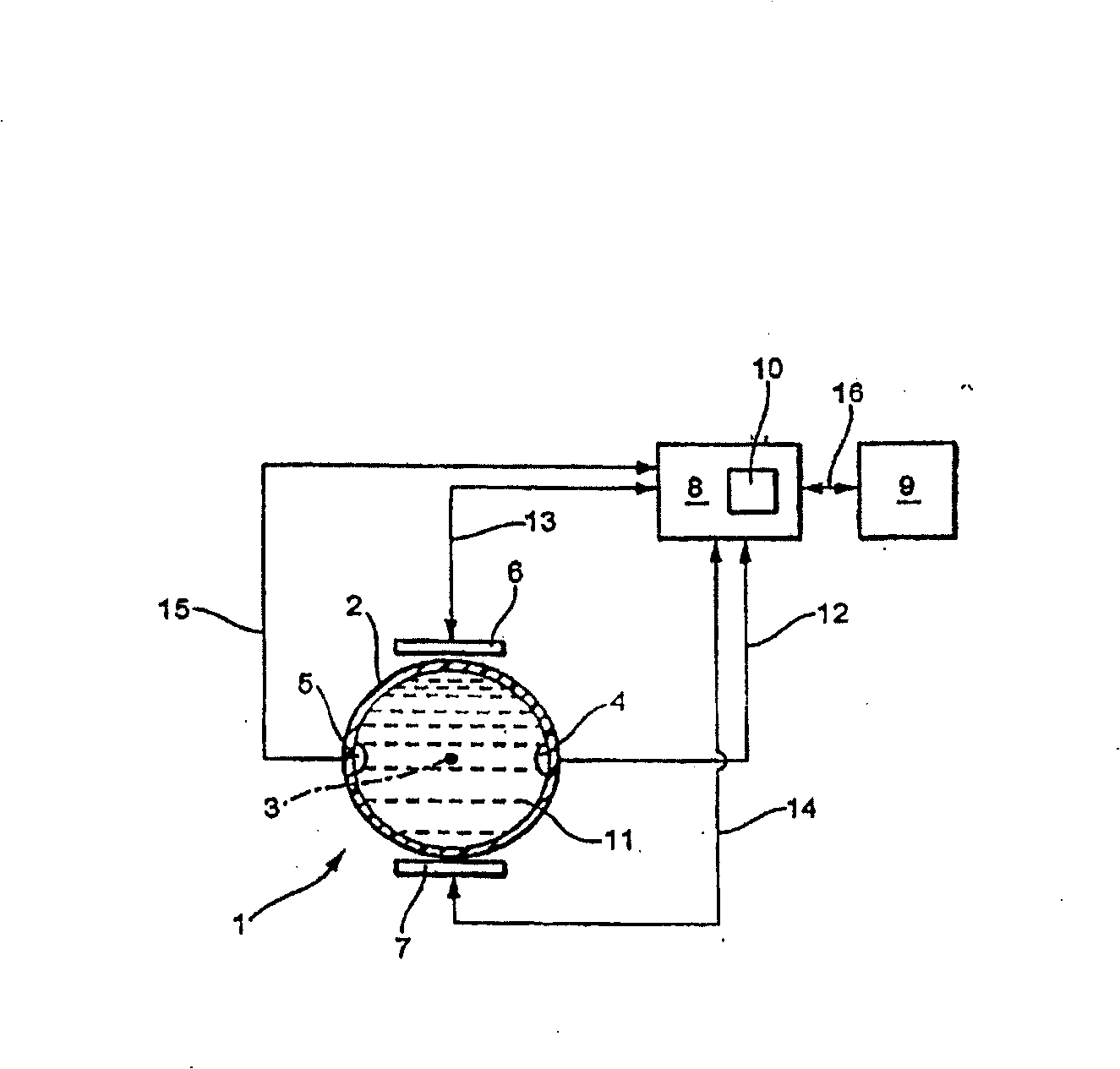
[0042] figure 1 A partial block diagram of a magnetic induction flowmeter suitable for the method of the present invention is shown schematically. With such a flow meter, a measured value of at least one physical quantity of a medium (in particular a fluid) flowing in a pipe (not shown) can be produced. For example, a flow meter can be used to measure the volumetric flow and / or flow rate of conductive liquids.

[0043] The flowmeter shown here comprises: a flow transmitter 1 for generating a measuring potential corresponding to the physical quantity to be measured; measuring instrument electronics with a microcomputer, which has, in particular, likewise at least partially implemented measurement using a microcomputer and an operating circuit 2 for detecting the measuring potential and for generating at least one measuring signal corresponding to the physical quantity; and an evaluation circuit 3 implemented in particular with a microcomputer for activating the measuring and o...


PUM


Abstract

The flow meter of the invention comprises a measuring tube for guiding the fluid to be measured and a magnetic field system with at least intermittently driven excitation current (I M ) through at least one magnetic field coil for generating a magnetic field at least partially perpendicular to the flow direction through the fluid. In the method of the present invention, at the second time point t 2 , will instantaneously drive the excitation current (I M ) voltage (U H ) from the second voltage level U drv Changed to, in particular, constant or adjusted to a constant third voltage level U short , to achieve an exciting current (I M ) current intensity from the maximum current value I m reduced to the field current (I M ) preset especially constant current final value I zu . In this case, select the third voltage level U short less than the second voltage level U rev . In order to determine the final value of the reached current I c The third time point t 3 , correspondingly at least intermittently detect the excitation current I M . Based on this determine the first time constant T for the magnetic field system short and / or the second time constant T rev +T short , where the first time constant T short at the second time point t 2 and the third time point t 3 between, corresponding to the time interval t 3 -t 2 , the second time constant T rev +T short at the first time point t 1 and the third time point t 3 between, corresponding to the time interval t 3 -t 1 . In order to determine the diagnostic value that finally represents the instantaneous working state of the flowmeter, the determined first time constant T short with a predetermined first reference value T 1ref compared and / or the determined second time constant T rev +T short with a predetermined second reference value T 2ref Compared.

Description

technical field [0001] The invention relates to a method for checking a magnetic induction flowmeter comprising a measuring tube for guiding a fluid to be measured and a magnetic field system with at least one magnetic field coil through which an excitation current flows at least intermittently For generating a magnetic field at least partially through the fluid perpendicular to the direction of flow. Background technique [0002] For measuring conductive fluids, flow meters using magnetic inductive flow transmitters are often employed. For the sake of simplicity, only flow transmitters or flowmeters will be used for description below if necessary according to the specific situation. Magnetic induction flowmeters are known which allow the measurement of the volume flow rate of an electrically conductive liquid flowing in a pipe and reflect this corresponding measurement; it is thus possible to measure the volume of liquid flowing through a pipe section per unit of time. Th...

Claims


Application Information

Patent Timeline
Patent Type & Authority Patents(China)
IPC IPC(8): G01F1/60G01F25/00
CPCG01F25/0007G01F1/60G01F25/10
Inventor 托马斯·布德米格
Owner ENDRESS HAUSER FLOWTEC AG
Features
  • R&D
  • Intellectual Property
  • Life Sciences
  • Materials
  • Tech Scout
  • Unparalleled Data Quality
  • Higher Quality Content
  • 60% Fewer Hallucinations
Learn More