Signal transmission circuit

A signal transmission and circuit technology, applied in transmission systems, circuit devices, wired transmission systems, etc., can solve the problems of chip load damage, high cost, lack of protection, etc., to achieve the effect of protecting the load and good load

Active Publication Date: 2009-01-28
HUAWEI TECH CO LTD
View PDF3 Cites 0 Cited by
  • Summary
  • Abstract
  • Description
  • Claims
  • Application Information

AI Technical Summary

Problems solved by technology

In the existing design mode of the protection circuit, if the differential mode and common mode protection devices are placed in the same position, or the differential mode protection device is placed before the common mode protection device, the differential mode protection device cannot suppress the differential mode caused by the above reasons. Interfering with the signal, so that it cannot play a good protective role;
[0007] 2. Balanced signal interface use figure 2 The cost of protection circuit 1 is relatively high. Therefore, in fact, protection circuit 2 is usually used for balanced signal interfaces containing isolation transformers, but protection circuit 2 is set before the isolation transformer. In the case of single-line to ground breakdown discharge, etc., which will cause common-mode interference to differential-mode interference, the differential-mode protection device will not be able to protect this, and the load with the chip in the subsequent stage will be damaged;
[0008] 3. For a balanced signal port, if an isolation transformer is used, and the transformation ratio of the isolation transformer is not a 1:1 transformer, but a 1:N (N is an integer greater than 1) transformer, then due to the differential mode The residual voltage of the protection device will be amplified and added to the signal input port of the load with the chip. The residual voltage is very easy to cause damage to the load with the chip, resulting in a defective design

Method used


Image

  • Signal transmission circuit
  • Signal transmission circuit
  • Signal transmission circuit

Examples


Embodiment Construction

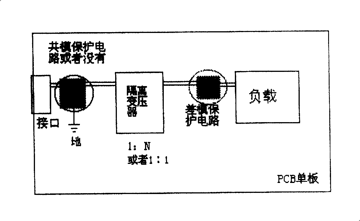
[0032] In order to achieve the purpose and effect of the above-mentioned invention, the preferred embodiments of the present invention are now described in detail in conjunction with the accompanying drawings as follows, please refer to image 3 , Figure 4 , Figure 5 :

[0033] Such as image 3 as shown, image 3 It is a preferred embodiment of the present invention. Its circuit includes: an interface module, a common-mode protection circuit connected to the interface module, an isolation transformer arranged after the common-mode protection circuit, a load with a chip, and an isolation transformer arranged between the isolation transformer and the load and close to the load Interface differential mode protection circuit;

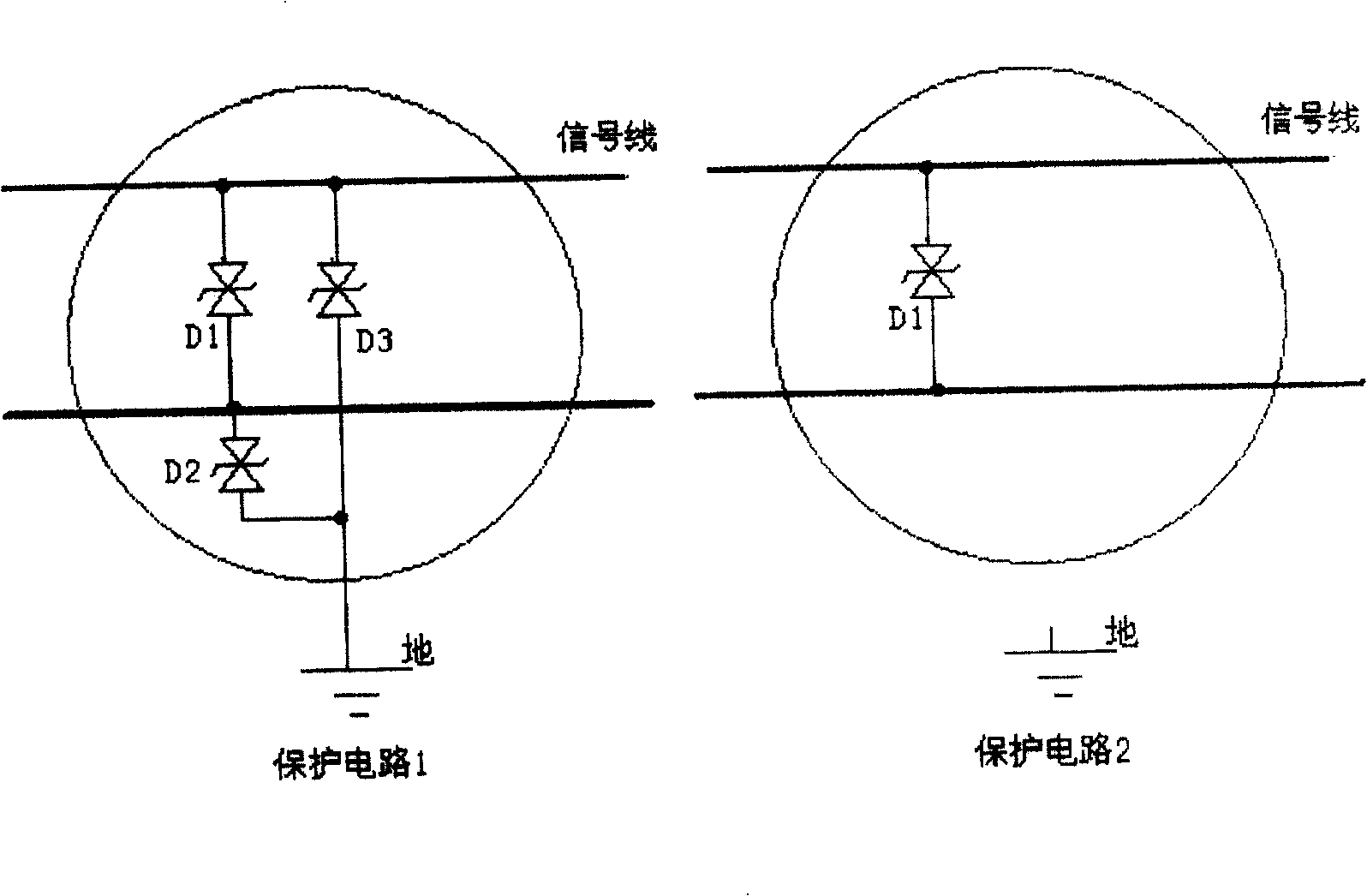
[0034] Such as Figure 4 as shown, Figure 4 For the common mode protection circuit, the protection circuit 1 is composed of transient diodes D2 and D3, and the protection circuit 2 is a schematic diagram of circuit connection when the common mode ...


PUM


Abstract

A signal transmission circuit with thunder proof function, whose signal port difference mode protection circuit is set in load interface with chip, common code protection circuit is set in input / output port of interface module. Said invention can suppress the common interference and difference mode interference resulting from thunder and adapt the protective design to use transformer with 1 : 1 and 1 : N in circuit.

Description

technical field [0001] The invention relates to a signal transmission circuit applied in the field of electronics and communication, in particular to a lightning protection signal port protection circuit of the signal transmission circuit. Background technique [0002] With the development of electronics and communication technology, the increasing status and importance of communication equipment and the increasing needs of users, on the one hand, the integration of electronics and communication chips is getting higher and higher, and the density of circuit design is getting higher and higher. On the other hand, It also requires greater adaptability and reliability of equipment operation. However, these two aspects are contradictory to each other. The higher the integration degree of electronic and communication products and the greater the circuit density, the weaker the anti-interference ability of chips, circuits or equipment, and the worse the stability and reliability. ...

Claims


Application Information

Patent Timeline
IPC IPC(8): H04B3/00H04B3/02H02H9/00
Inventor 陈敦利王庆海
Owner HUAWEI TECH CO LTD
Why Eureka
Try Eureka