
Flexible track drilling machine

一种轨道、两轨道的技术,应用在计算机控制、金属加工机械零件、程序控制等方向,能够解决尚未提供大范围工件解决办法等问题,达到编程简化的效果

Inactive Publication Date: 2009-02-04
THE BOEING CO
View PDF7 Cites 4 Cited by
  • Summary
  • Abstract
  • Description
  • Claims
  • Application Information

AI Technical Summary

Problems solved by technology

[0002] The problem of accurately drilling holes in large workpieces such as aircraft wings and fuselage panels or other types of structures has always been a challenge to the aircraft industry and other industries, and so far has not provided a fully satisfactory, The solution for a wide range of workpiece constructions
[0004] It is possible to install a pair of spaced apart rails on a compound contoured surface such that the rails are equally spaced at all points along the rail, but only by custom designing the rails for a specific workpiece surface

Method used


Image

  • Flexible track drilling machine
  • Flexible track drilling machine
  • Flexible track drilling machine

Examples


Embodiment Construction

[0022] Hereinafter, the present invention will be described more fully with reference to the accompanying drawings, in which the preferred embodiments of the present invention are shown. However, the present invention can be implemented in many different forms and should not be considered limited to the embodiments described herein; rather, these embodiments are provided so that the disclosure will be thorough and complete, and the present invention The category is fully conveyed to those skilled in the art. The same reference numerals indicate the same elements throughout.

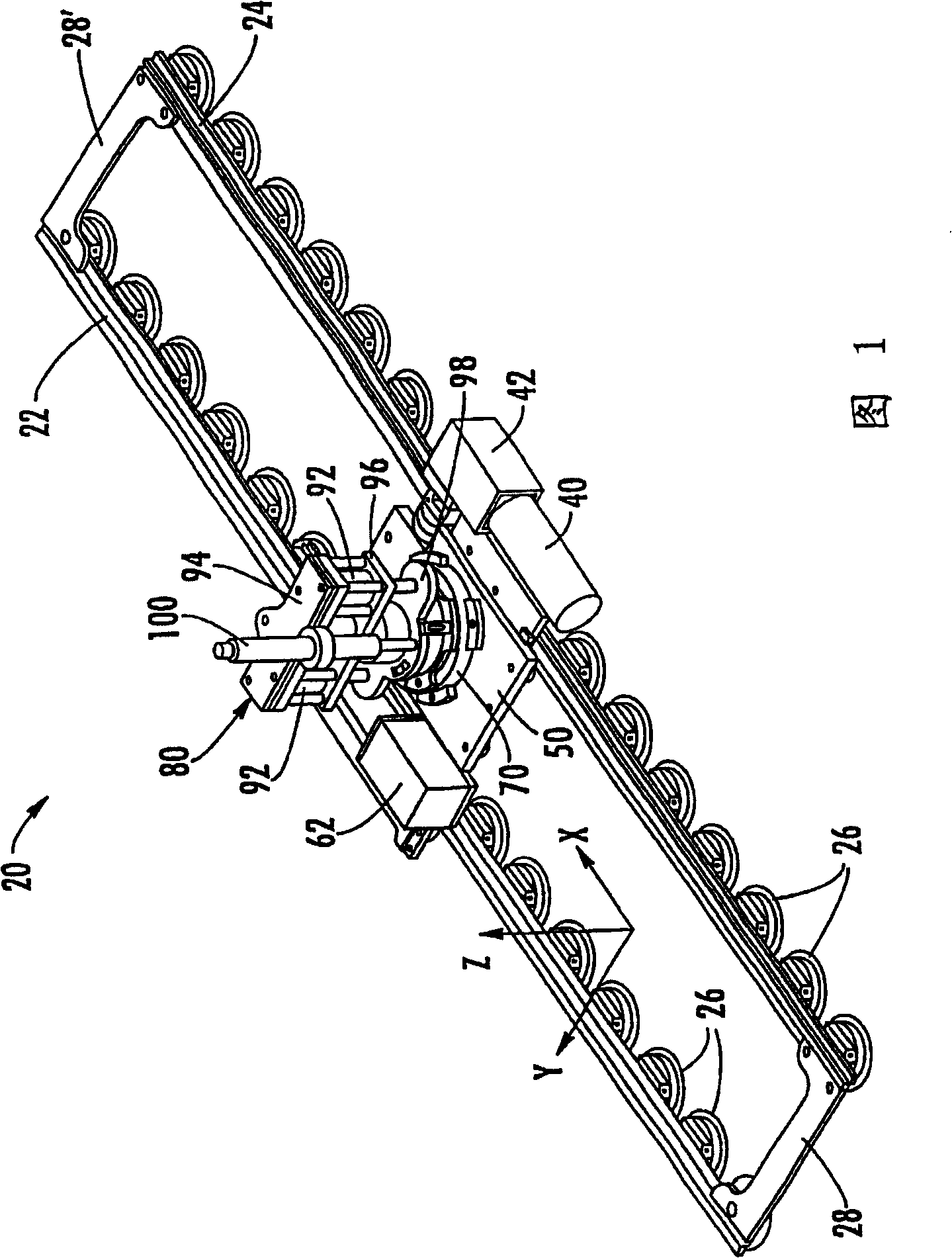
[0023] Referring to Figure 1, this figure shows a machine 20 according to a preferred embodiment of the present invention. This machine includes a pair of rails 22, 24, a plurality of attachment devices, preferably in the form of a vacuum cup holder assembly 26, which are detachably fixed to the pair of rails at spaced intervals along the length of each rail. The rails 22, 24 preferably have a width significa...


PUM


Abstract

The present invention discloses a flexible rail drilling machine that employs a pair of rails that are flexible in one direction to accommodate non-flat workpiece surfaces and are substantially rigid in a direction parallel to the workpiece surface of. The rails are attached to the workpiece by vacuum cup holders spaced along each rail. The X-axis bracket is slidably mounted on the track through rollers mounted on a flexible spring plate fixed to the bracket. A drill or other device to be positioned is mounted on a Y-axis carriage that is slidably connected to an X-axis carriage. The three-dimensional workpiece surface is mathematically transformed into a two-dimensional flat pattern, and the positioning of the carriage is controlled based on the flat pattern.

Description

Technical field [0001] The present invention relates to a machine for drilling holes or performing other processing operations on large workpieces, such as panels or similar components constructed in simple or combined contours, such as the wings and fuselage parts of airplanes. The present invention more specifically relates to a flexible rail machine and method, which locates a drilling machine, an imprinting machine or the like with respect to the workpiece by reciprocating a processing module along a rail mounted on the workpiece and positioned on the workpiece Processing module. Background technique [0002] The problem of precision drilling on large workpieces such as aircraft wings and fuselage panels or other types of structures has always been a challenge for the aircraft industry and other industries, and therefore, so far has not provided a completely satisfactory, It is a solution suitable for a wide range of workpiece structures. Large fixed pile machines such as fiv...

Claims


Application Information

Patent Timeline
Patent Type & Authority Patents(China)
IPC IPC(8): B23Q9/00B23Q1/26B23Q1/62G05B19/408
CPCB23Q9/0042B23Q9/0014B23Q1/26B23Q1/621B23Q9/0007Y10T409/306384
Inventor 西奥多·M·博伊尔-戴维斯小詹姆斯·N·巴特里克罗杰·A·盖奇达雷尔·D·琼斯科斯坦迪诺斯·D·帕佩尼科拉奥
Owner THE BOEING CO
Learn More