
High magneto-resistance magnetic sensor and method for producing the magnetic sensor

A magnetic sensor and giant magnetoresistance technology, which is applied in the fields of magnetic field controlled resistors, flux-sensitive magnetic heads, instruments, etc., can solve the limitations of the use environment and scope of application of magnetic-sensitive devices, loss of function, and inability to guarantee performance and quality. Uniformity and other issues to achieve the effect of improving sensitivity and testing accuracy, stabilizing performance and quality, and facilitating industrial implementation

Inactive Publication Date: 2008-07-02
HEFEI INSTITUTES OF PHYSICAL SCIENCE - CHINESE ACAD OF SCI
View PDF1 Cites 12 Cited by
  • Summary
  • Abstract
  • Description
  • Claims
  • Application Information

AI Technical Summary

Problems solved by technology

However, this magnetic sensitive device has disadvantages. First, it is difficult to make the magnetic field lines of the magnetic field emitted by the permanent magnet attached to the back of the magnetic sensitive device strictly parallel to the plane where the multilayer film is located, thereby reducing its response to the magnetic field. Sensitivity and test accuracy cannot guarantee the uniformity of performance and quality when it becomes a mass product; secondly, the increase in ambient or working temperature will easily soften the epoxy glue, causing the displacement of the permanent magnet, which in turn affects its Sensitivity and accuracy; again, harsh workplaces, such as in a shaking or vibrating working environment, can easily cause permanent magnets to fall off, resulting in loss of function; finally, as a permanent magnet that provides a bias magnetic field, once it is pasted on the magnetic After the back of the sensitive device, its magnetic field strength can no longer be adjusted, so that the use environment and scope of application of the magnetic sensitive device are greatly restricted

Method used


Image

  • High magneto-resistance magnetic sensor and method for producing the magnetic sensor
  • High magneto-resistance magnetic sensor and method for producing the magnetic sensor
  • High magneto-resistance magnetic sensor and method for producing the magnetic sensor

Examples


Embodiment Construction

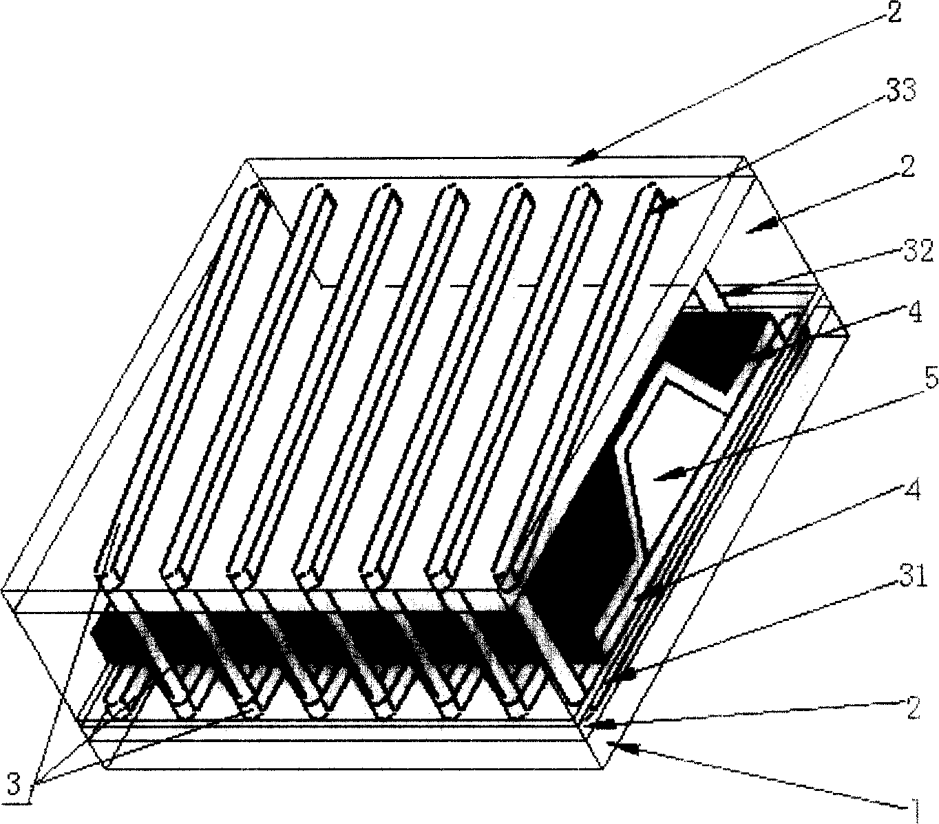
[0014] see figure 1 , The giant magnetoresistive magnetic sensor is composed of an insulating layer 2 and a coil 3 placed on the substrate 1, and a ferromagnetic layer 4 sandwiching a conductive layer 5 is set in the coil 3. Wherein, the substrate 1 is a silicon wafer. The thickness of the ferromagnetic layer 4 is 10 nm, and the ferromagnet in the ferromagnetic layer 4 is made of amorphous FeCoSiB (FeCoSiB). The thickness of the conductive layer 5 is 10 nm, and the conductor in the conductive layer 5 is made of metallic copper. The coil 3 is a micro solenoid formed by a sputtering process, which is composed of a coil lower wire 31 obtained by a metal copper sputtering process, a coil vertical wire 32 and a coil upper layer wire 33, wherein the coil lower wire 31 The width of the wire 33 on the upper layer of the coil and the coil is 0.5 micron, and the thickness is 0.5 micron; the winding direction of the coil 3 is perpendicular to the current direction of the conductive lay...


PUM

PropertyMeasurementUnit
sizeaaaaaaaaaa
widthaaaaaaaaaa
thicknessaaaaaaaaaa

Abstract

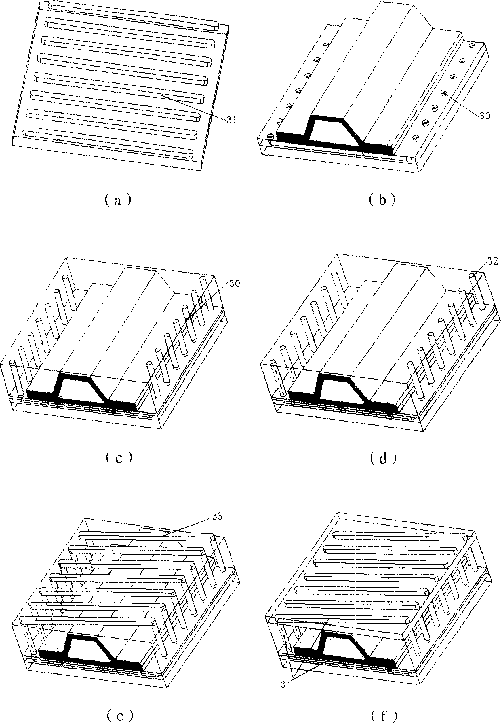
The invention discloses a magnetic sensor with huge magnetoresistance and a preparation method thereof. The sensor comprises a substrate (1), an insulating layer (2) on the substrate, a ferromagnetic layer (4) wrapped with a conductive layer (5). In particularly, a loop (3) is coated on the ferromagnetic layer (4) wrapped with the conductive layer (5), and the loop (3) and the ferromagnetic layer (4) are both covered by the insulating layer (2). The method is realized by respectively repeated adoption of technologies, including mask, lithography or ion etching, DC magnetic control sputtering, magnetic control sputtering of radio frequency or improving chemical vapor deposition with plasmas, and processing technology of a semiconductor membrane in sequence to carve, sputter and generate a lower lead layer of the loop, a lower insulating layer, the magnetoresistance sensor comprising the ferromagnetic layer, the conductive layer and another ferromagnetic layer, a medium insulating layer, a vertical lead of the loop, an upper lead layer of the loop, and an upper insulating layer on the substrate. Afterwards, the lower lead layer, the vertical lead and the upper lead layer of the loop are electrically connected, thus obtaining the magnetic sensor with huge magnetoresistance. The invention has high precision and sensitivity and is beneficial for industrial production.

Description

technical field [0001] The invention relates to a sensor and a manufacturing method, in particular to a giant magnetoresistive magnetic sensor and a manufacturing method thereof. Background technique [0002] The giant magnetoresistance effect is a new phenomenon discovered in the past 10 years. When a constant high-frequency current is passed through a material with a giant magnetic effect, a weak external magnetic field change can cause a significant change in the impedance of the material, and the change rate can be as high as 50%. Due to the excellent magnetic field sensitivity of the giant magnetoresistance material, the stability and reliability of the detection can still be maintained even without introducing any amplification equipment into the external electronic circuit. The characteristics and applying it to the weak magnetic field detector will greatly improve the accuracy and precision of direction detection. At present, people have made some attempts and effo...

Claims


Application Information

Patent Timeline
Patent Type & Authority Applications(China)
IPC IPC(8): H01L43/08G01R33/09G11B5/39H10N50/10
Inventor 李新化邱凯尹志军钟飞姬长建陈家荣王玉琦林新华陈池来高理升
Owner HEFEI INSTITUTES OF PHYSICAL SCIENCE - CHINESE ACAD OF SCI
Learn More