
Encapsulation structure for preventing adhesive crystal glue from polluting wafer welding cushion and substrate thereof

A technology for chips and pads, which is applied in the field of packaging structures and substrates to prevent chip pads from being polluted by adhesive glue. Component and cost effects

Inactive Publication Date: 2009-02-18
CHIPMOS TECH INC
View PDF7 Cites 0 Cited by
  • Summary
  • Abstract
  • Description
  • Claims
  • Application Information

AI Technical Summary

Problems solved by technology

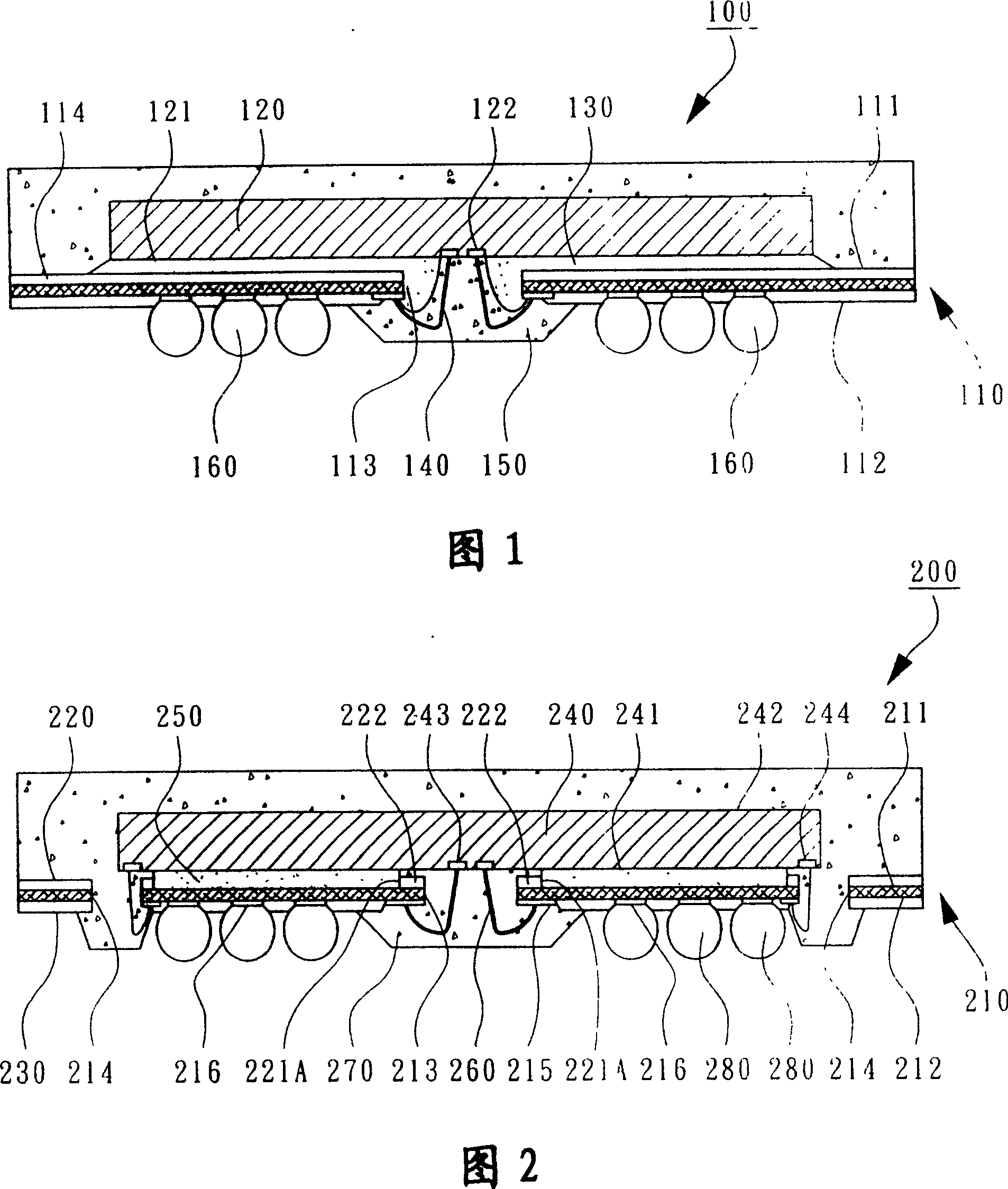
However, if a low-cost pasty die-bonding glue is used, the die-bonding glue 130 will be fluid when heated, and will contaminate the plurality of pads 122 of the chip 120 or even the substrate when heated and squeezed. 110 of the wire bonding fingers, causing the plurality of bonding wires 140 to not stick to the plurality of bonding pads 122 and / or the plurality of wire bonding fingers
Even if the width of the wire bonding channel 113 is designed to be more enlarged, relatively the edge of the encapsulant 150 covering the wire bonding fingers is closer to the positions of the plurality of solder balls 160, so that the substrate 110 is used to connect the plurality of solder balls. The ball pads of the ball 160 will also have the problem of contamination, so the packaging defect rate cannot be reduced, and it cannot be applied to high-density COB packaging
[0004] It can be seen that the above-mentioned existing "chip on board" semiconductor packaging structure obviously still has inconvenience and defects in structure and use, and needs to be further improved urgently.
In order to solve the above-mentioned problems, the relevant manufacturers have tried their best to find a solution, but no suitable design has been developed for a long time, and the general products do not have a suitable structure to solve the above-mentioned problems. This is obviously related. The problem that the industry is eager to solve

Method used


Image

  • Encapsulation structure for preventing adhesive crystal glue from polluting wafer welding cushion and substrate thereof
  • Encapsulation structure for preventing adhesive crystal glue from polluting wafer welding cushion and substrate thereof
  • Encapsulation structure for preventing adhesive crystal glue from polluting wafer welding cushion and substrate thereof

Examples


no. 1 Embodiment

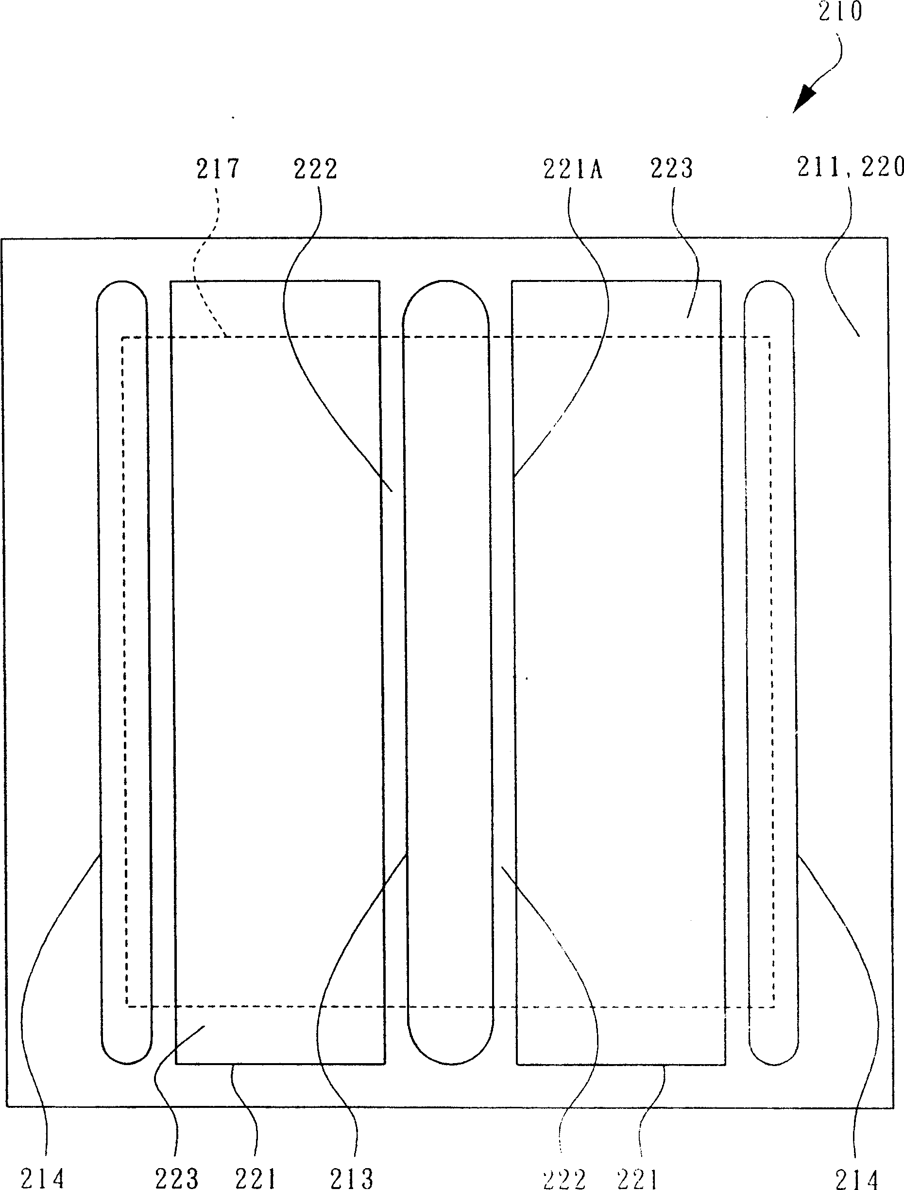
[0077] According to the first specific embodiment of the present invention, FIG. 2 is a schematic cross-sectional view of a packaging structure for preventing die-bonding glue from contaminating chip pads. image 3 A schematic diagram of the upper surface of the substrate used for the package construction, Figure 4A 4C is a schematic cross-sectional view of the substrate during the die-bonding process.

[0078] As shown in FIG. 2 , a packaging structure 200 for preventing chip pads from being polluted by the die-bonding glue mainly includes a substrate 210 , a chip 240 , a die-bonding glue 250 , a plurality of bonding wires 260 and an encapsulant 270 . Usually, the substrate 210 can be a printed circuit board, which has an upper surface 211, a lower surface 212, and a plurality of wire bonding channels 213, 214, wherein the plurality of wire bonding channels 213, 214 can be elongated slots, And penetrate the upper surface 211 and the lower surface 212 for the plurality of bon...


PUM


Abstract

The invention relates to an encapsulating structure for preventing wafer adhesives polluting wafer pads and the baseplate thereof. The encapsulating structure is in a form of on-plate wafer encapsulation, mainly comprising a plate, a wafer, wafer adhesive, a plurality of bond wires and an encapsulating colloid. The baseplate has at least one wire bond channel, and a solder-preventing layer on a wafer-adhering surface of the baseplate has at least one adhesive leading aperture to form solder-preventing bars on the two sides of the wire bond channel, thereby preventing the wafer adhesive polluting the wafer pad during adhering the wafer. Therefore, the pasty wafer adhesive of low cost can replace the prior glue-film wafer adhesive with no need of enlarging the width of the wire bond channel, which meets the requirement of high density encapsulation and adds no more elements.

Description

technical field [0001] The present invention relates to a "Chip-On-Board (COB)" type semiconductor packaging technology, in particular to a packaging structure and a substrate for preventing chip bonding pads from being polluted by a die-bonding glue. Background technique [0002] "Chip on Board" (COB, also known as Board-On-Chip, BOC) by companies such as Texas Instruments (TI) or individuals, has been widely used in the packaging of high-frequency memory and high-performance chips, chip paste On the substrate or the carrier of the printed circuit board, and wire bonding technology can be used to electrically connect the chip and the substrate. In the past, the die-bonding material used for die-bonding was PI adhesive film, but the component cost was too high and the amount of tape waste was large. Therefore, it is hoped to use pasty die-bonding adhesive instead, but the overflow of the die-bonding adhesive will lead to an increase in the packaging failure rate. [0003] A...

Claims


Application Information

Patent Timeline
Patent Type & Authority Patents(China)
IPC IPC(8): H01L23/498H01L23/31
CPCH01L2924/15311H01L2224/73215H01L2224/32225H01L2224/4824H01L2924/3025H01L2924/181H01L2924/00H01L2924/00012
Inventor 林鸿村
Owner CHIPMOS TECH INC
Learn More