A fluidized spray drying granulator
A technology of fluidized spraying and fluidized granulation, which is applied to granulators in the production of granular products in the chemical industry, medicine, and food fields. It can solve the problems of long production cycle, high production cost, and discounted production efficiency to achieve increased fog The effect of optimizing the scope, shortening the working cycle and improving production efficiency
- Summary
- Abstract
- Description
- Claims
- Application Information
AI Technical Summary
Problems solved by technology
Method used
Image
Examples
Embodiment 1
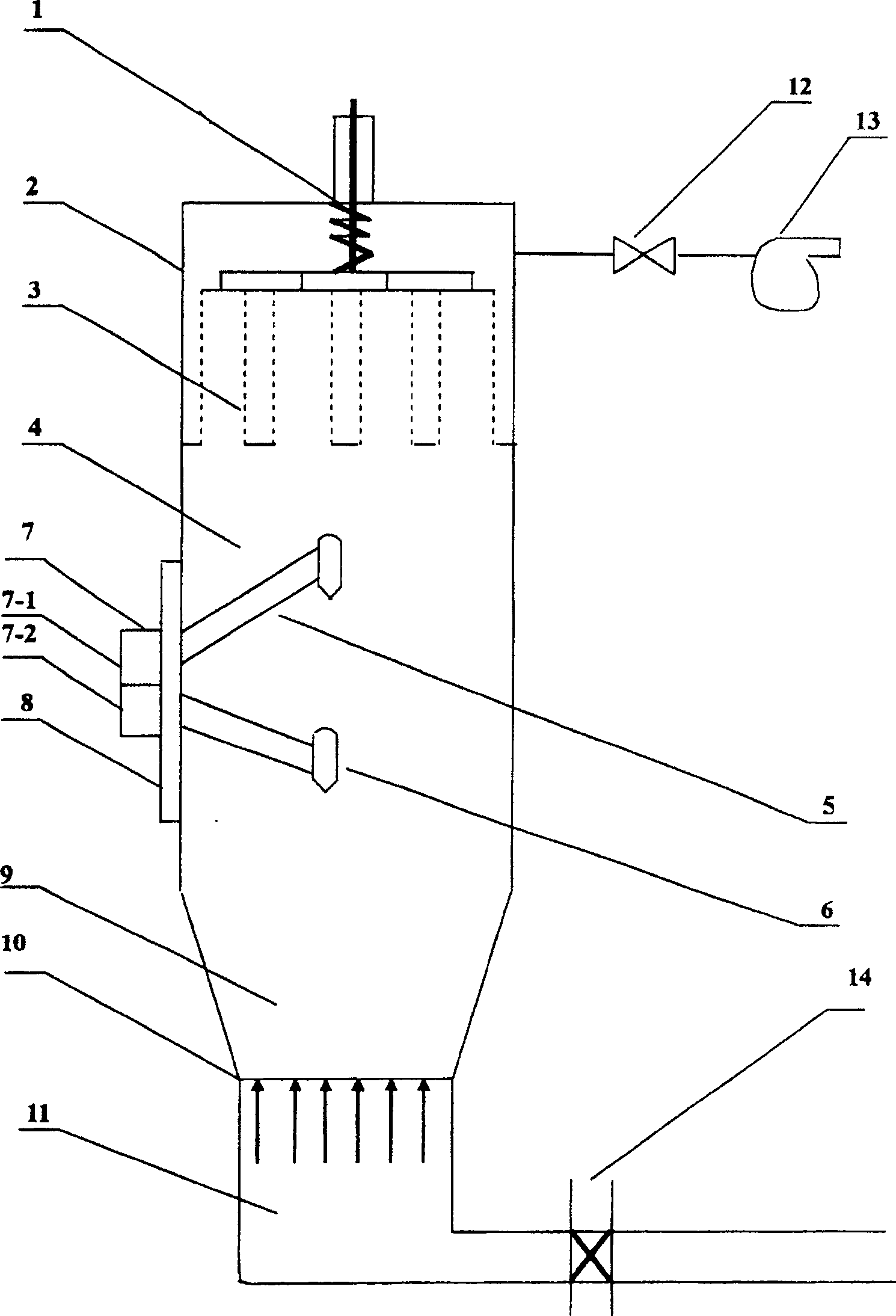
[0027] In this preferred embodiment, two spray guns 5-1 and 5-2 are provided. In addition, a spray drying chamber 4 is set between the trapping chamber 2 and the boiling fluidized granulation chamber 9, and the top of the trapping chamber 2 is provided with a shaking bag cylinder 1 and a trapping bag 3, and a centrifugal fan 13 is connected to the upper part. The bottom of the boiling fluidized granulation chamber 9 is provided with an air flow distribution plate 10 , and the lower part is provided with an air supply chamber 11 and a regulating valve 14 . The spray gun is located at the junction of the spray drying chamber 4 and the boiling fluidized granulation chamber 9 .
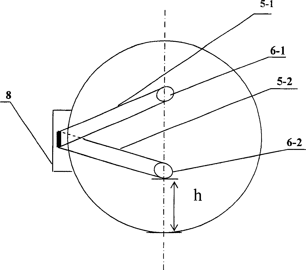
[0028] Such as figure 1 with figure 2 As shown, in this embodiment, spray gun brackets 7-1 and 7-2 arranged vertically and vertically at a stepless adjustment plate 8 installed in the tank body of the spray drying chamber, spray guns 5-1 and 5 -2 are installed on the spray gun brackets 7-1 and 7-2 res...
Embodiment 2
[0031] Such as figure 1 with Figure 4 As shown, in this embodiment, the spray gun brackets 7-1 and 7-2 arranged vertically up and down in sequence are arranged at the stepless adjustment plate 8 installed in the tank body of the spray drying chamber, and the spray guns 5-1 and 5-2 Installed on spray gun brackets 7-1 and 7-2 respectively, the two spray guns 5-1 and 5-2 are in different horizontal planes and vertical planes. The positions of the two spray guns 5-1 and 5-2 can be adjusted along the longitudinal axis of the granulator with the stepless adjustment plate. Preferably, the included angle θ of the two spray guns in the horizontal plane is 45°, the linear distance between the spray heads 6-1 and 6-2 in the horizontal projection plane is 550mm, and the shortest distance h between the spray heads and the inner wall of the tank is 400mm (see Figure 4 ). All the other structures are the same as in Embodiment 1.
Embodiment 3
[0033] In this example, if Figure 5 As shown, the two spray guns 5-1 and 5-2 are respectively installed on two stepless adjustment plates 8-1 and 8-2 on the same horizontal horizontal axis of the granulator, and the stepless adjustment plate 8-1 is located at 8 Opposite side of -2. The positions of the two spray guns 5-1 and 5-2 can be adjusted along the longitudinal axis of the granulator with the stepless adjustment plate. Preferably, the linear distance between the nozzles 6-1 and 6-2 of the spray gun is 600mm, and the shortest distance h between the two nozzles and the inner wall of the tank is 400mm. More preferably, the distance between the stepless adjustment plates 8-1 and 8-2 is equal. All the other structures are the same as in Embodiment 1.
PUM
| Property | Measurement | Unit |
|---|---|---|
| particle size | aaaaa | aaaaa |
| density | aaaaa | aaaaa |
Abstract
Description
Claims
Application Information
 - R&D
- Intellectual Property
- Life Sciences
- Materials
- Tech Scout
- Unparalleled Data Quality
- Higher Quality Content
- 60% Fewer Hallucinations
Browse by: Latest US Patents, China's latest patents, Technical Efficacy Thesaurus, Application Domain, Technology Topic, Popular Technical Reports.
© 2025 PatSnap. All rights reserved.Legal|Privacy policy|Modern Slavery Act Transparency Statement|Sitemap|About US| Contact US: help@patsnap.com


