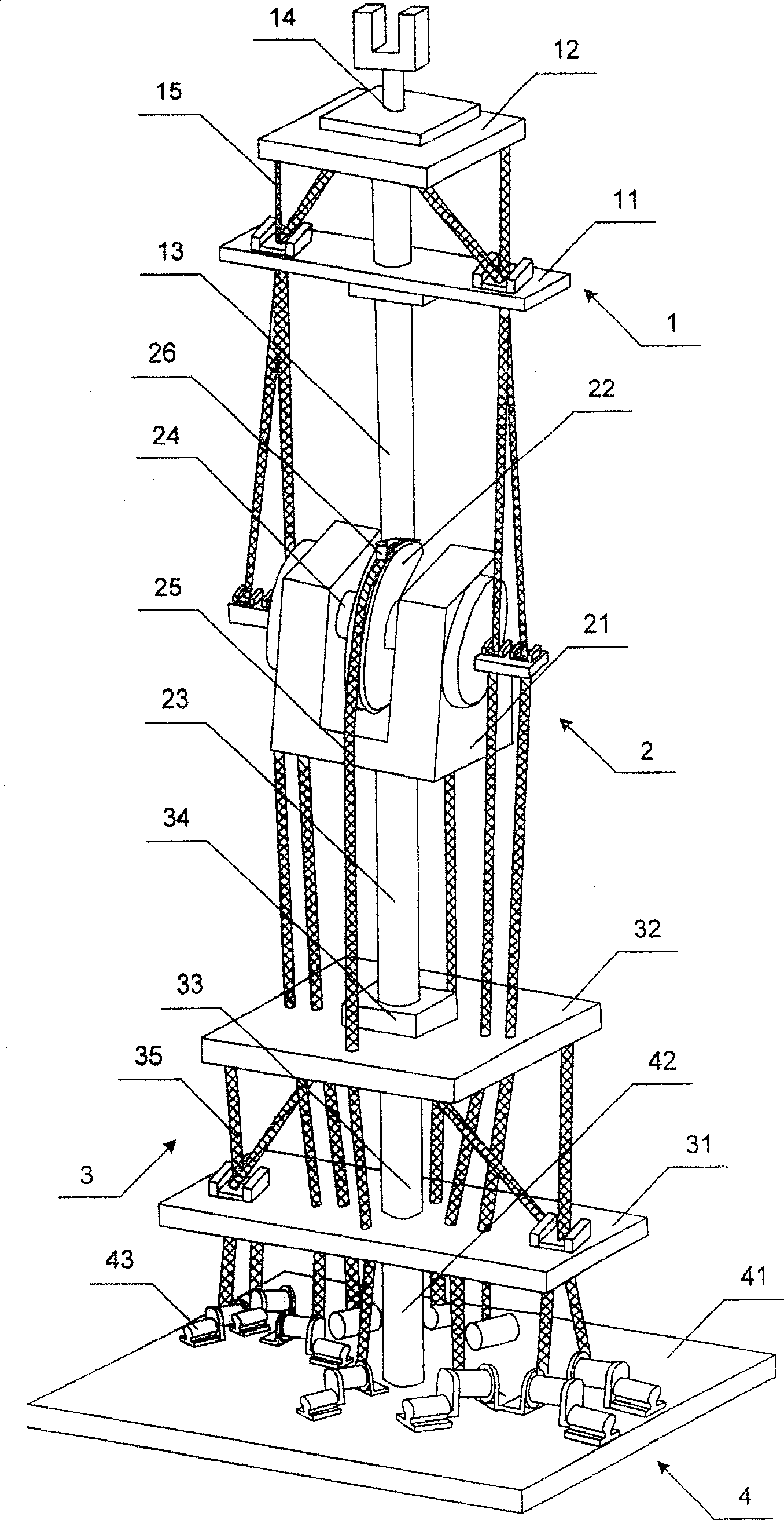
A rope-driven redundancy mechanical arm
A technology of redundancy and manipulators, applied in the direction of manipulators, claw arms, joints, etc., can solve the problems that affect the control accuracy and the elbow joint is prone to slipping, so as to achieve good control accuracy and eliminate slipping problems
- Summary
- Abstract
- Description
- Claims
- Application Information
AI Technical Summary
Problems solved by technology
Method used
Image
Examples
no. 1 example
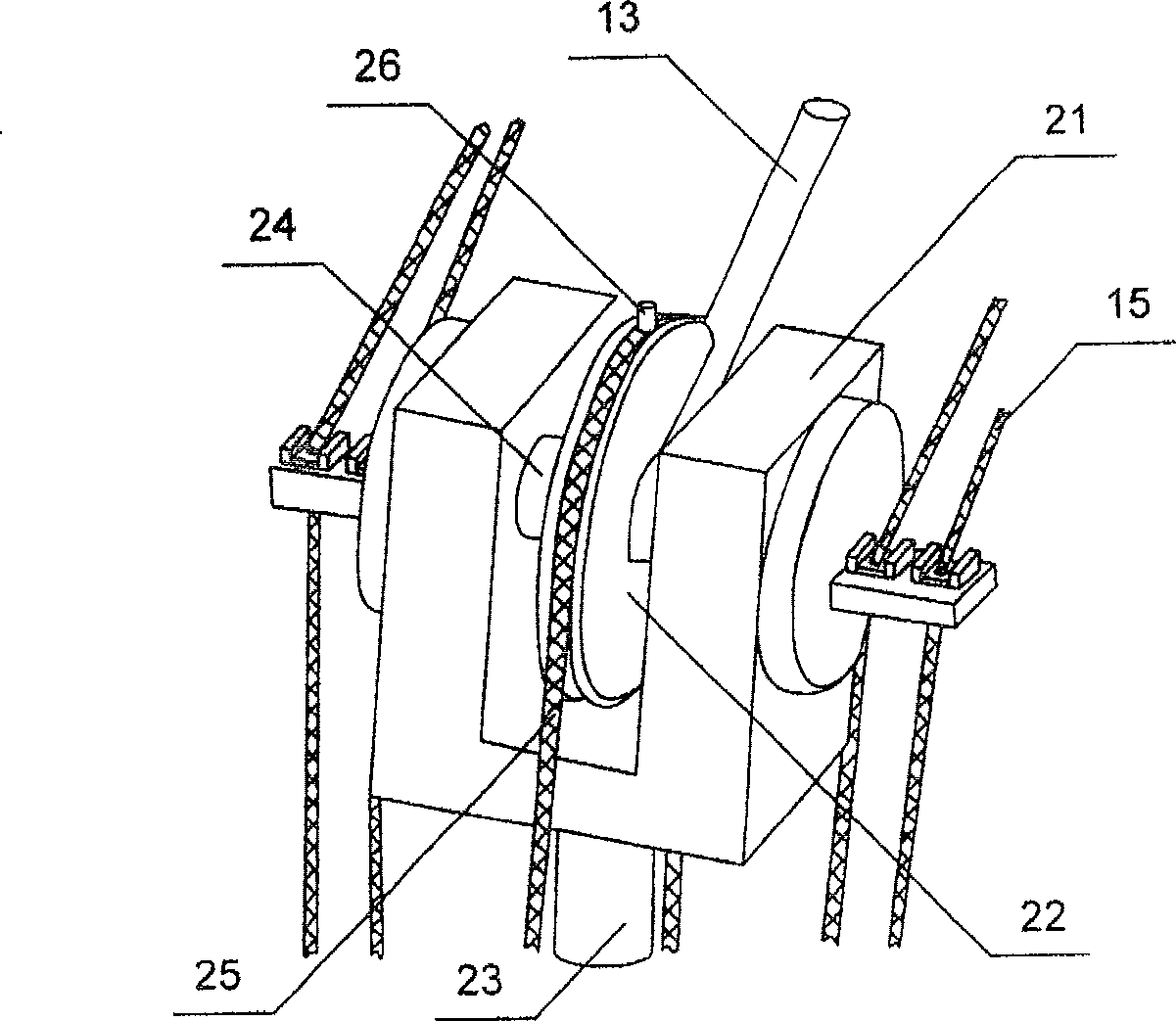
[0028] In this embodiment, the drive wheel 22 is provided with a stop cone, and the elbow joint control rope 25 is provided with a stop cone. Specifically, the stop cone hole is a groove provided on the top of the transmission wheel 22, the stop cone is a protrusion fixed on the elbow joint manipulation rope 25, and the protrusion fixed on the elbow joint manipulation rope 25 is inserted into the transmission wheel. In the groove that 22 tops offer, the transmission wheel 22 of this position and the elbow joint control rope 25 are relatively fixed. When the elbow joint control rope 25 pulls the transmission wheel 22 to rotate, due to the limitation of the protrusions and grooves, the elbow joint control rope 25 will not slip and has good control accuracy, which meets the requirements for high-speed movement and quick response of the mechanical arm. It can also be implemented very well.
[0029]In this embodiment, the stop taper hole and the stop cone body can have multiple re...
no. 2 example
[0031] In this embodiment, a stopper cone is set on the transmission wheel 22, and a stopper cone hole is set on the elbow joint manipulation rope 25. Specifically, the stop cone hole is a groove or a through hole provided on the elbow joint manipulation rope 25, and the stop cone is a protrusion provided on the top of the transmission wheel 22, and the protrusion provided on the top of the transmission wheel 22 is inserted into the elbow joint manipulation rope 25. In the groove or the through hole on the rope 25, the transmission wheel 22 of this position and the elbow joint manipulation rope 25 are relatively fixed. When the elbow joint control rope 25 pulls the transmission wheel 22 to rotate, due to the limitation of the protrusions and grooves, the elbow joint control rope 25 will not slip and has good control accuracy, which meets the requirements for high-speed movement and quick response of the mechanical arm. It can also be implemented very well.
[0032] In this em...
no. 3 example
[0034] In this embodiment, a stop cone is set on the drive wheel 22, and the elbow joint manipulation rope 25 is fixedly connected to the stop cone. Specifically, the stopper cone is a protrusion provided on the top of the transmission wheel 22. The protrusion can be a cylinder, a cone, a rectangle and a structure commonly used by those skilled in the art. Clamping, winding, etc. are fixedly connected to the protrusion, so that the transmission wheel 22 and the elbow joint control rope 25 at this position are relatively fixed, and the winding method is the most convenient.
PUM
 Abstract
Description
Claims
Application Information
 - R&D
- Intellectual Property
- Life Sciences
- Materials
- Tech Scout
- Unparalleled Data Quality
- Higher Quality Content
- 60% Fewer Hallucinations
Browse by: Latest US Patents, China's latest patents, Technical Efficacy Thesaurus, Application Domain, Technology Topic, Popular Technical Reports.
© 2025 PatSnap. All rights reserved.Legal|Privacy policy|Modern Slavery Act Transparency Statement|Sitemap|About US| Contact US: help@patsnap.com


