A screw nail

A screw and thread technology, applied in the field of screw-fixing products, can solve the problems of outward expansion of objects, damage to the appearance of objects, and difficulty in screwing operations, and achieve the effect of improving use efficiency and cutting labor.

Inactive Publication Date: 2009-03-04
徐国泰
View PDF7 Cites 0 Cited by
  • Summary
  • Abstract
  • Description
  • Claims
  • Application Information

AI Technical Summary

Problems solved by technology

[0003] However, for the "screw improvement" of the above two cases and the "screw that integrates locking, stability, labor-saving, fast and multifunctional", the present invention still feels that there should be room for improvement; for example, No. 556784 "Screw Improvement" "In the new patent case, although the rod has the structural function of cutting and collecting chips, when the screw starts to screw into an object such as wood, it is hindered by the hardness of the object, so the staff still needs to operate with considerable force, resulting in In the locking operation, there is still the lack of difficulty in the screw-in operation; another example is the new patent case No. 289405 "Screw that integrates stable locking, labor-saving, fast and multi-functional", although its rod has a cutting chip removal structure Function, but the rod is screwed into the middle to the rear of the object. Because the crumbs cannot be discharged, the rod is pushed outward to the surrounding tissue of the object, so that the object expands outward, and even seriously damages the appearance of the object.
[0004] In view of the above-mentioned two new patents, the present invention still has multiple functions such as cutting, chip removal and chip collection in the process of screw fixing, which is not ideal. Therefore, it has been engaged in this technical field for many years. Professional experience, in order to seek product excellence and innovative concepts, especially to improve and innovate the above-mentioned deficiencies of the screws, here, finally successfully developed a screw that can be locked at the same time, due to its structure. The function of fast cutting, chip removal and chip collection is integrated in one design to achieve the utilization value of this industry

Method used


Image

  • A screw nail
  • A screw nail
  • A screw nail

Examples


Embodiment Construction

[0025] Regarding the screw of the present invention, the technical means adopted and the effect of achieving the above-mentioned purpose are easy to understand. Hereby, a detailed description is made with the best embodiment in conjunction with the simple description of the drawings and the symbols of each component as follows:

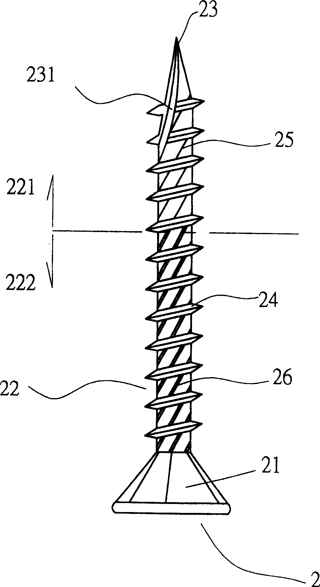
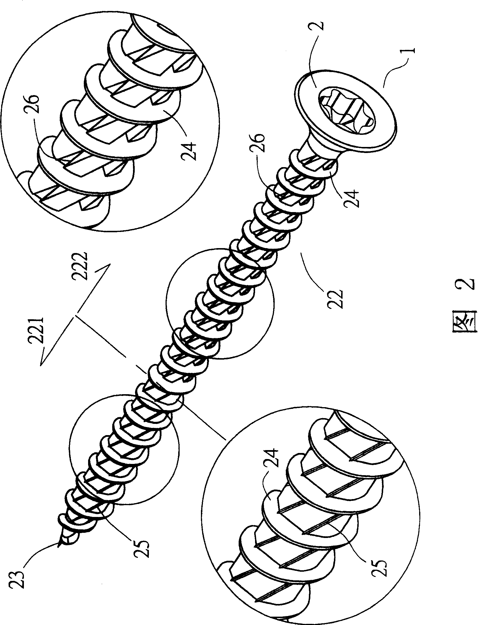
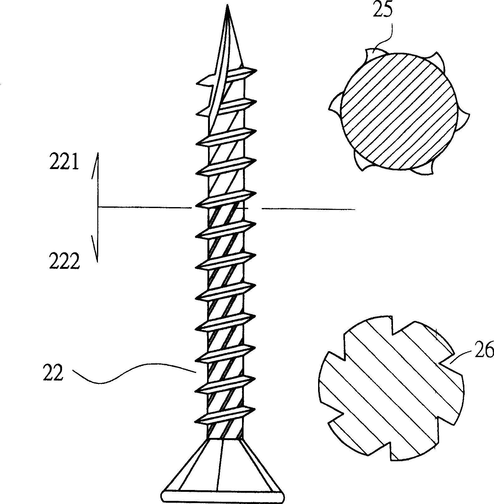
[0026] First, please also see Figure 1 to Figure 3 As shown, the screw 2 designed by the present invention includes a head 21, a shank 22, a tip 23, and a plurality of threads 24 integrally formed on the shank 21 and coiled continuously in a helical shape; wherein:

[0027] The shank 22 of the screw 2 is provided with several outer convex cutting parts 25 at the front section 221 having the thread 24 in the direction of the tip 23, so that the front section 221 can be screwed into the object 3 to smoothly complete the cutting and quick discharge. The first stage of crumb work is shown in Figure 2 and Figure 4 shown; in addition, the above-mentioned...


PUM


Abstract

The invention publicizes a screw that comprises a head, a rod, a tip and multi continuous coiling screw threads formed on the rod. A protruding cutting section is set on the threaded front facing the tip on the rod to allow the front successfully finishing the first stage of process for cutting and quick chip removal while screwing to the working piece. An inward concave cutting section is set on the threaded back to allow the back part inserted into the working piece with smooth completion of the second stage process of cutting and quick chip removal. Apart from that, a cutting groove can be set at the tip of the screw or set several cutting teeth outside of the thread to enhance the ability of quick screwing the tip of the screw. With the above design, a screw fastening device is formed with the features of laborsaving cutting, quick chip removal and chip collecting.

Description

technical field [0001] The present invention relates to a screw, in particular to a screw with a convex cutting part and a concave cutting part respectively located between the screw threads, so that the screw can form a multi-layer structure with labor-saving cutting, fast chip removal and chip collection. Effective screw products. Background technique [0002] With the advancement of various industrial technologies, the structural design of the current screw has been developed from only simple locking to focusing on the work efficiency in the locking process and not destroying the integrity of the object to be locked, which can be achieved by the present invention New patents such as No. 556784 "Screw Improvement" and No. 289405 "Screws that integrate locking, stability, labor, speed, and multiple functions" in the Taiwan Patent Gazette that were designed earlier, approved and published as the main screws Representatives, it can be clearly seen that the two cases not only...

Claims


Application Information

Patent Timeline
Patent Type & Authority Patents(China)
IPC IPC(8): F16B25/04
Inventor 徐国泰
Owner 徐国泰
Why Eureka
Try Eureka