Encoding circuit for triggering signals of PWM three level inverter and control of compensation of the dead zone
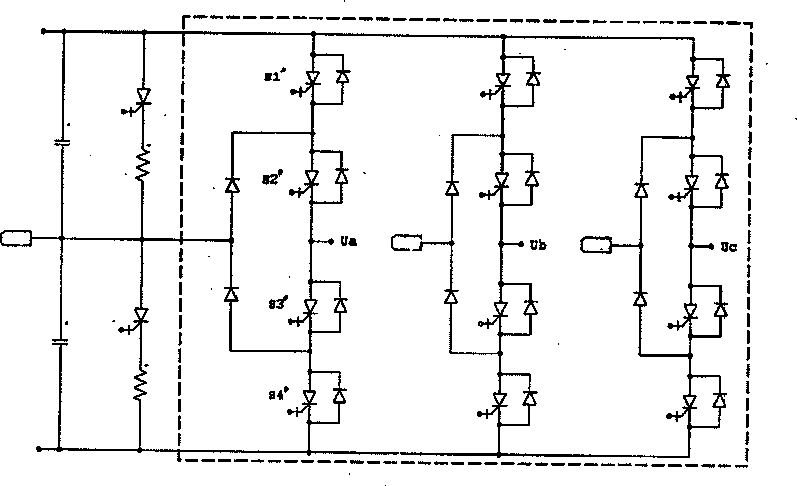
A technology of three-level inverter and decoding circuit, which is applied in the field of power transformation, can solve problems such as the complexity of 12-way PWM control signals, achieve wide industrial applicability, ensure safe operation, and reduce harmonic content
- Summary
- Abstract
- Description
- Claims
- Application Information
AI Technical Summary
Problems solved by technology
Method used
Image
Examples
Embodiment Construction
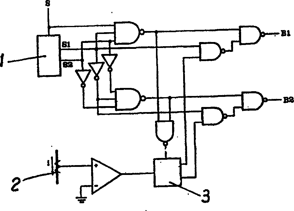
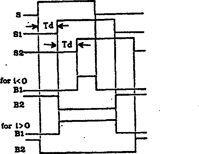
[0024] The decoding circuit of the present invention is composed of an encoder and three groups of logic delay circuits. The three pairs of PWM modulation signals output by the encoder are respectively input into a corresponding group of logic delay circuits, and after simple logic operation and delay processing, the control signals for controlling the switching devices of the three-phase bridge arms of the inverter are output. Since each group of logic delay circuits is the same, they are all composed of a two-input AND gate AND, a two-input OR gate OR, two NOT gates and four delayers DELAY. Therefore, a detailed explanation will be given by taking one group as an example.
[0025] see Figure 4 As shown, in order to perform PWM modulation on the three-level inverter, the encoder (not shown in the figure) sends a pair of modulation signals to each phase of the inverter circuit, that is, the first modulation signal PWM1 and the second modulation signal PWM2. The first modula...
PUM
 Abstract
Description
Claims
Application Information
 - R&D
- Intellectual Property
- Life Sciences
- Materials
- Tech Scout
- Unparalleled Data Quality
- Higher Quality Content
- 60% Fewer Hallucinations
Browse by: Latest US Patents, China's latest patents, Technical Efficacy Thesaurus, Application Domain, Technology Topic, Popular Technical Reports.
© 2025 PatSnap. All rights reserved.Legal|Privacy policy|Modern Slavery Act Transparency Statement|Sitemap|About US| Contact US: help@patsnap.com


