Optical film for setting a microlens on upper radial of prism

An optical film and microlens technology, applied in optics, prisms, optical components, etc., can solve the problems of increasing the brightness of the optical axis, increasing the complexity and cost, increasing the installation of related components, volume and cost, etc., to increase the brightness of the optical axis. , the effect of gain light characteristics

Inactive Publication Date: 2009-03-18
APTICON
View PDF5 Cites 0 Cited by
  • Summary
  • Abstract
  • Description
  • Claims
  • Application Information

AI Technical Summary

Problems solved by technology

[0002] figure 1 Shown is the known optical film, which includes a prism layer (P) arranged and connected on a base layer (B). The structure of the prism is used to achieve the required optical characteristics, but this known optical film If you want to increase the on-axis brightness, you must design and change the angle and direction of the prism, which will increase the complexity and cost of production. The direction of the optical axis will also increase the installation, volume and cost of related components
[0003] In the prior art, no one has ever tried to directly add a light-guiding structure on the prism surface of the prism. The inventor of this case first invented this direct, cheap and effective way to guide the light emitted from the prism surface close to the optical axis. , an optical film that increases the brightness of the optical axis

Method used


Image

  • Optical film for setting a microlens on upper radial of prism
  • Optical film for setting a microlens on upper radial of prism
  • Optical film for setting a microlens on upper radial of prism

Examples


Embodiment Construction

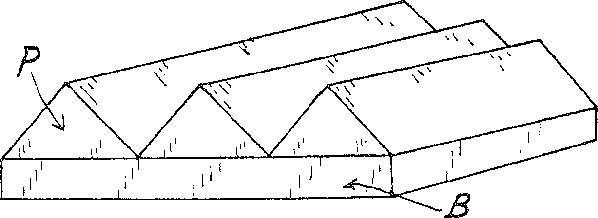
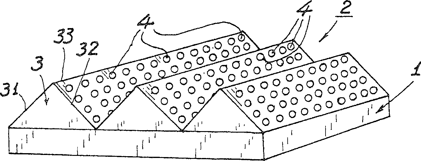
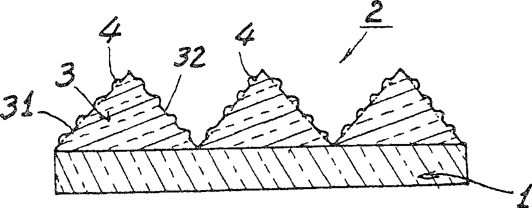
[0026] refer to figure 2 , image 3 , Figure 4 , the optical film of the present invention comprises: a transparent base layer 1; A plurality of micro-lenses 4 (micor-lenses), including convex lenses and concave lenses, are provided continuously or integrally formed.

[0027] The cross-section of each microlens 4 can be in shapes such as arc, crescent, semicircle, and its bottom surface and prism surface 31 or 32 are coplanar (coplanar); Or the bottom surface of 32 takes the inflection point (I, Inflection point) of the microlens as its vertex outwardly in the direction away from the prism surface and gradually convexes (covex).

[0028] The microlens 4 should be integrally formed on the prism surfaces 31, 32 of each prism; and the prism 3 and the microlens 4 can be integrally formed on the base layer 1 by molding or transfer printing. superior.

[0029] The transparent base layer 1 can be made of thermoplastic resins, including polystyrene dicarboxylate (PET), polycarb...


PUM


Abstract

The invention comprises a transparent base layer and a prism layer containing multi prisms and located on said transparent base layer. It features the following: multi micro lenses are located on the surface of the prism; by passing through the micro lenses, the light projected on the prism will be outputted in a direction more trending to the optical axis so as to increase the brightness of the optical film.

Description

technical field [0001] The invention relates to an optical film with micro-lenses arranged on the surface of a prism. Background technique [0002] figure 1 Shown is the known optical film, which includes a prism layer (P) arranged and connected on a base layer (B). The structure of the prism is used to achieve the required optical characteristics, but this known optical film If you want to increase the on-axis brightness, you must design and change the angle and direction of the prism, which will increase the complexity and cost of production. The direction of the optical axis will also increase the installation, volume and cost of related components. [0003] In the prior art, no one has ever tried to directly add a light-guiding structure on the prism surface of the prism. The inventor of this case first invented this direct, cheap and effective way to guide the light emitted from the prism surface close to the optical axis. , an optical film that increases the brightn...

Claims


Application Information

Patent Timeline
Patent Type & Authority Patents(China)
IPC IPC(8): G02B5/04G02B1/00
Inventor 林清彬
Owner APTICON
Why Eureka
Try Eureka