
Backlight control circuit capable of automatically adjusting voltage and control method for luminous element

A backlight control and automatic adjustment technology, applied in electrical components, electroluminescent light sources, electric light sources, etc., can solve the problems of energy consumption, increase of output voltage Vout, etc., and achieve the effect of saving energy consumption

Active Publication Date: 2009-04-01
RICHTEK TECH
View PDF3 Cites 0 Cited by
  • Summary
  • Abstract
  • Description
  • Claims
  • Application Information

AI Technical Summary

Problems solved by technology

The disadvantage caused by it is that the output voltage Vout also increases correspondingly, causing unnecessary energy consumption

Method used


Image

  • Backlight control circuit capable of automatically adjusting voltage and control method for luminous element
  • Backlight control circuit capable of automatically adjusting voltage and control method for luminous element
  • Backlight control circuit capable of automatically adjusting voltage and control method for luminous element

Examples


Embodiment Construction

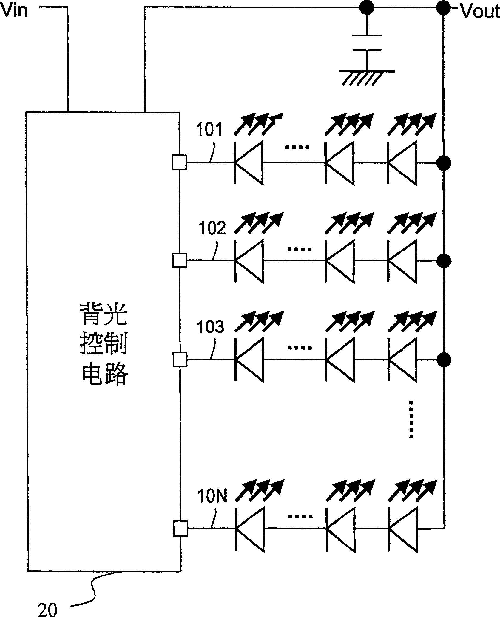
[0069] Please refer to Figure 4 , wherein one of the embodiments of the invention is shown as a schematic circuit diagram. As shown in the figure, in the backlight control circuit 30 of this embodiment, corresponding current sources CS1-CSN (represented by circuit blocks) are provided on each of the parallel light-emitting diode paths 101-10N for controlling the current sources on the corresponding paths. current flow. (The LED path 101-10N refers to the entire path from the node of the output voltage Vout to the ground.) Different from the prior art, in this embodiment, the lowest voltage and the reference voltage among the nodes N11-N1N are not selected For Vref comparison, a high-low voltage comparison amplifying circuit 29 is used; The function of the voltage comparison amplifier circuit 29 is to compare the voltage signal representing the current state on the LED path 101-10N.

[0070] The voltage signal representing the current state, for example, can select the node...


PUM


Abstract

The present invention discloses an automatic voltage adjusting backlight control circuit, which comprises a voltage supply circuit, a plurality of nodes and a high-low circuit comparing mu-circuit. The voltage supply circuit receives an input voltage and is controlled by a control signal and produces an output voltage; the voltage of each node represents the current value in a corresponding luminescent component path; the high-low circuit comparing mu-circuit can produce the control signal according to the voltage difference between a plurality of nodes. The present invention provides an automatic dynamic state adjusting balance mechanism. The backlight control circuit can automatically adjust and reduce an output voltage Vout until the difference between the highest voltage and the lowest voltage is equal to the preset valve. With the present invention, the object of energy saving is realized and the problem that a reference voltage Vref value is difficult to be artificially set is avoided.

Description

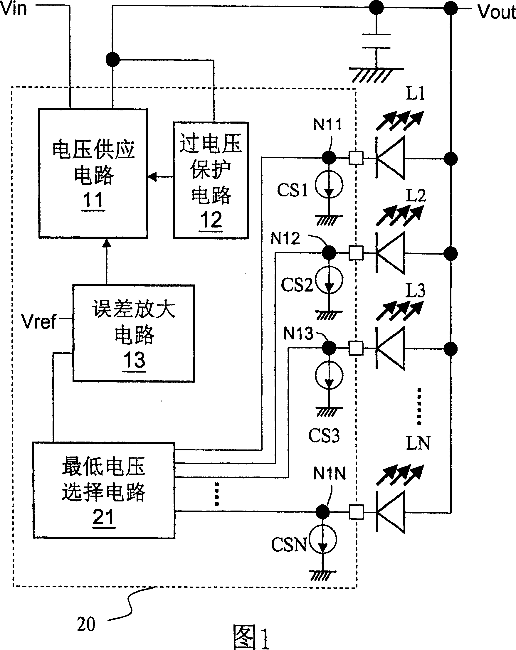
technical field [0001] The invention relates to a backlight control circuit (Backlight Control Circuit), in particular to a backlight control circuit capable of automatically adjusting the supply voltage of a light-emitting diode to optimize energy consumption efficiency. Background technique [0002] In the liquid crystal display device, the backlight control circuit is used to control the light-emitting diodes to emit light from the back of the liquid crystal screen, so that users can watch the images on the screen. [0003] Please refer to FIG. 1 , which is an example of a prior art backlight control circuit when LEDs are fully connected in parallel. As shown in the figure, the currents of the LEDs L1-LN in the backlight control circuit 20 are respectively controlled by the current sources CS1-CSN. The backlight control circuit 20 includes a lowest voltage selection circuit 21 for selecting the lowest voltage among the cathode terminals of all light emitting diodes L1-LN...

Claims


Application Information

Patent Timeline
Patent Type & Authority Patents(China)
IPC IPC(8): H05B33/08G09G3/34H05B44/00
Inventor 刘景萌
Owner RICHTEK TECH
Learn More