Blade type engine

An engine and vane technology, applied in the field of fuel vane engines, can solve the problems of low engine efficiency, low conversion efficiency, unsatisfactory efficiency, etc., and achieve the effects of high fuel and transmission efficiency, simple structure and small volume

Inactive Publication Date: 2009-04-08
崔德云
View PDF4 Cites 0 Cited by
  • Summary
  • Abstract
  • Description
  • Claims
  • Application Information

AI Technical Summary

Problems solved by technology

[0002] The currently used fuel engines are crankshaft-connecting rod mechanism type, the efficiency of this engine is low, and when the mechanism is at the top dead center, the cylinder pressure is the highest, but the conversion efficiency is the lowest, which is zero
Then it is restricted by the ratio of the radius of the crankshaft to the connecting rod, and the efficiency is not ideal. Although people have tried to improve it and achieved some results, they have not fundamentally solved its inherent defects.

Method used


Image

  • Blade type engine
  • Blade type engine
  • Blade type engine

Examples


Embodiment Construction

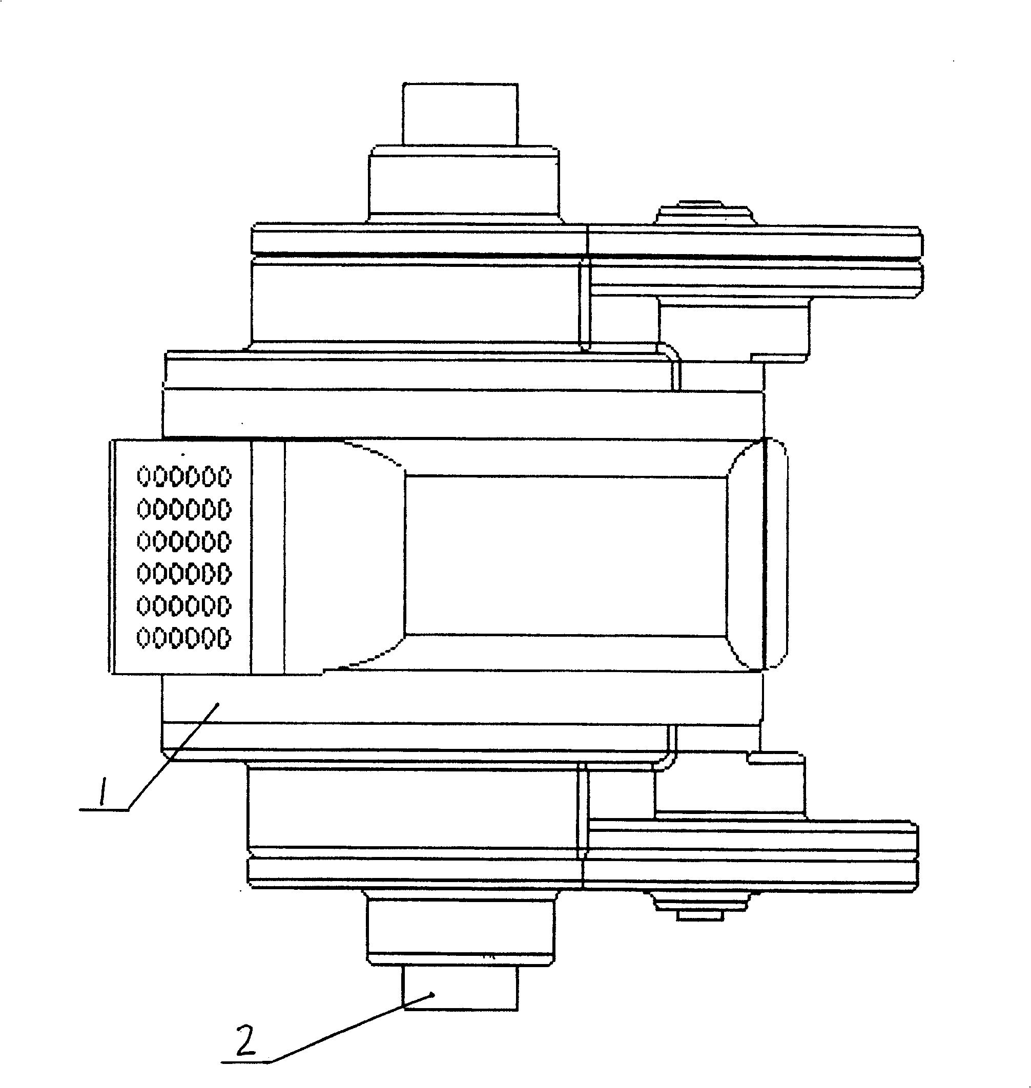
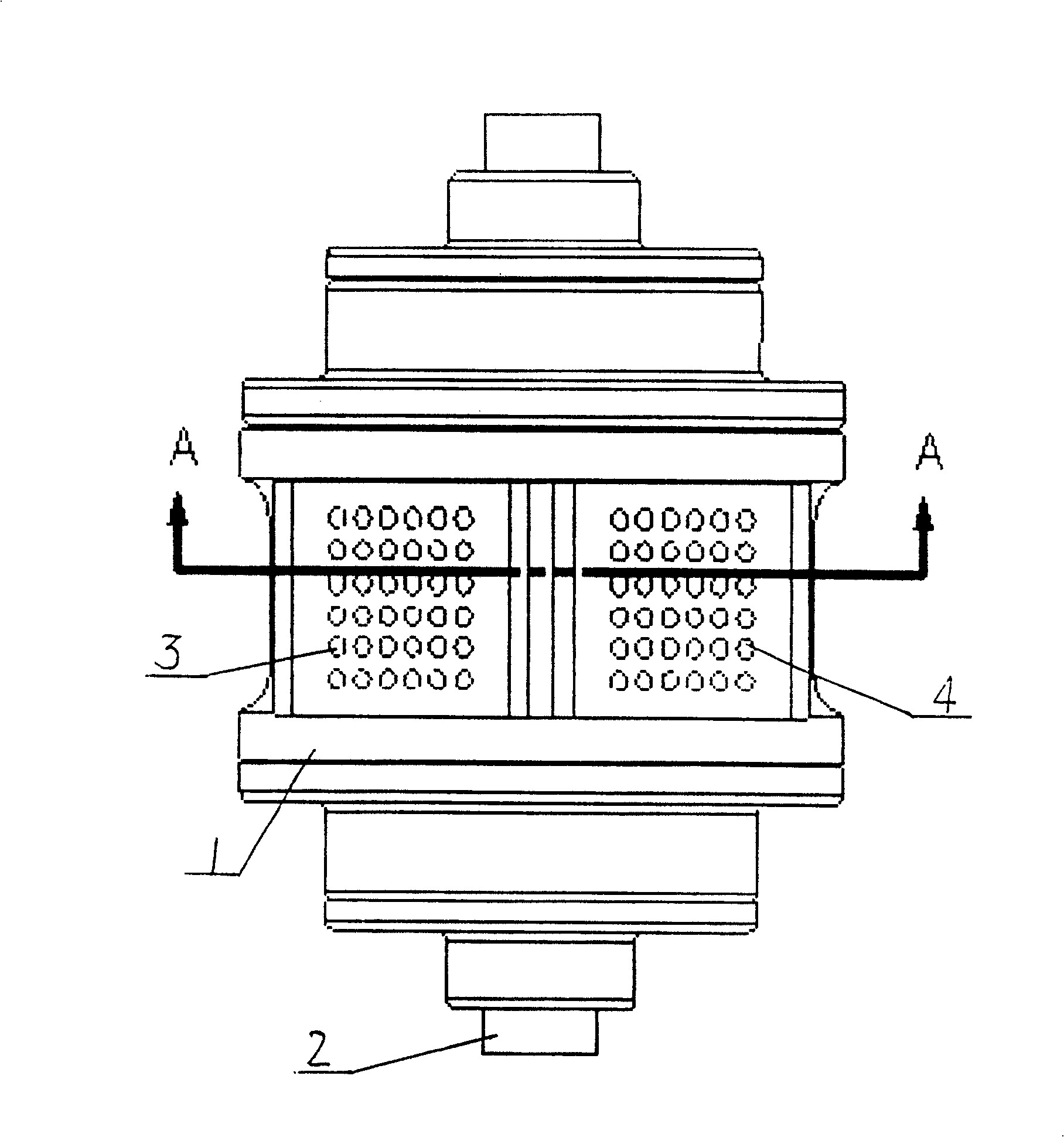
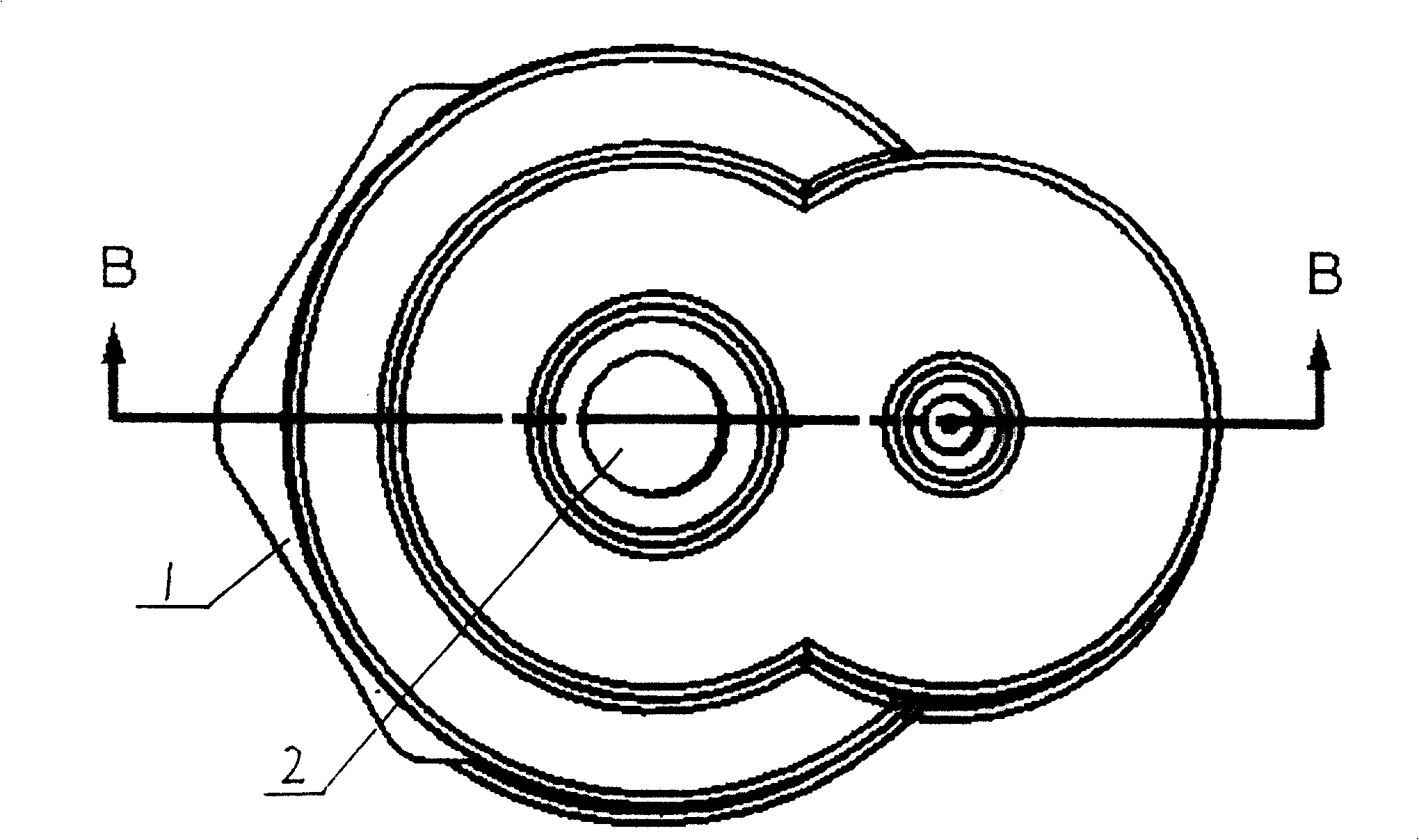
[0012] As shown in the drawings, the engine shaft 2 is fixed in the casing 1 through bearings, and the left and right blades 5, 6 are vacantly sleeved on the engine shaft 2 in the casing 1 through the bushing 12. The left and right blades 5 and 6 are slidingly matched with the casing 1 in a small gap, and there are cylindrical grooves on the left and right blades 5 and 6. 1 cooperate to form four chambers 7, so that the left and right blades 5 and 6 can move at variable speeds within the scope of the four chambers 7. Fixed left large spur gear 8 on the left blade 5, as Figure 5 As shown, the left small cylindrical gear 11 meshing with the left large cylindrical gear 8 is fixed on the casing 1 through a bearing, and the oval gear 10 is coaxially fixed with the left small cylindrical gear 11, and another transmission parameter meshing with the oval gear 10 is the same Oval gear 9 is fixed with described engine shaft 2. The transmission ratio of the left large cylindrical gear...


PUM


Abstract

The invention relates to fuel oil vane type engine, the engine is fixed in the shell through a bearing, the left and right vanes are covered above the engine shaft in the shell, and the two vanes are buckled together, and forms four cavities together with the shell; the left vane is fixed on the left cylinder gear, the left small cylinder gear matching with the large cylinder gear is arranged on the shell, a elliptical gear coaxial to the small cylinder gear is assembled, the other elliptical gear with the same parameter to the first one and engaged with the first elliptical gear is fixed to the engine, the gearing ratio of the two cylinder gear is 2:1; the structure and the gearing relation of the right vane to the engine shaft is the same to the one from the left vane to the engine shaft, what is the difference is that the axial direction of the two elliptical gears mismatch about 180 degrees; there arranges with air inlet, discharging outlet and firing device on the shell of the left and right vane and the four cavities.

Description

(1) Technical field [0001] The invention relates to a fuel vane engine. (two), background technology [0002] Currently used fuel engines are all crankshaft-connecting rod mechanism type, the efficiency of this engine is low, and when the mechanism is at the top dead center, the cylinder pressure is the highest, but the conversion efficiency is the lowest, which is zero. Restricted by the ratio of the radius of the crankshaft to the connecting rod, the efficiency is not ideal. Although people have tried to improve it and achieved some results, they have not fundamentally solved its inherent defects. (3) Contents of the invention [0003] In order to overcome the disadvantages of the prior art, the present invention provides a vane engine, which eliminates the crankshaft connecting rod mechanism, and uses vanes to directly convert the kinetic energy generated by the fuel into rotational kinetic energy. Simple structure, small volume, fuel saving and high efficiency. [00...

Claims


Application Information

Patent Timeline
Patent Type & Authority Patents(China)
IPC IPC(8): F02B53/00F01B9/06
CPCY02T10/17Y02T10/12
Inventor 崔德云
Owner 崔德云
Why Eureka
Try Eureka