
Dead-point-free oscillating hydrofoil type tidal current energy power generation structural body

A technology with no dead point and tidal energy, applied in the directions of hydropower generation, ocean energy power generation, engine components, etc., it can solve the problems of increasing design difficulty, high starting flow rate, poor replaceability, etc., achieving easy modular assembly and reducing manufacturing costs. , The effect of convenient overall disassembly

Active Publication Date: 2021-06-18
HARBIN INST OF TECH AT WEIHAI
View PDF8 Cites 0 Cited by
  • Summary
  • Abstract
  • Description
  • Claims
  • Application Information

AI Technical Summary

Problems solved by technology

When the flywheel is used to overcome the dead point, due to the large moment of inertia of the flywheel, a large starting torque is required when the mechanism is started, so the required starting flow rate is large, which limits the application area of ​​the power generation device, and the design of the flywheel needs to be accurately calculated. Flywheel needs special processing, poor replaceability
The link mechanism used to transmit the heave and pitch motion of the hydrofoil often has high requirements on the space position, so the size of the flywheel cannot be designed arbitrarily, which greatly increases the difficulty of design
However, when the dead point is overcome by dislocation arrangement, the mechanism cannot maintain complete symmetry, and in applications requiring symmetrical mechanisms, the dislocation arrangement method will be limited

Method used


Image

  • Dead-point-free oscillating hydrofoil type tidal current energy power generation structural body
  • Dead-point-free oscillating hydrofoil type tidal current energy power generation structural body
  • Dead-point-free oscillating hydrofoil type tidal current energy power generation structural body

Examples


specific Embodiment approach 1

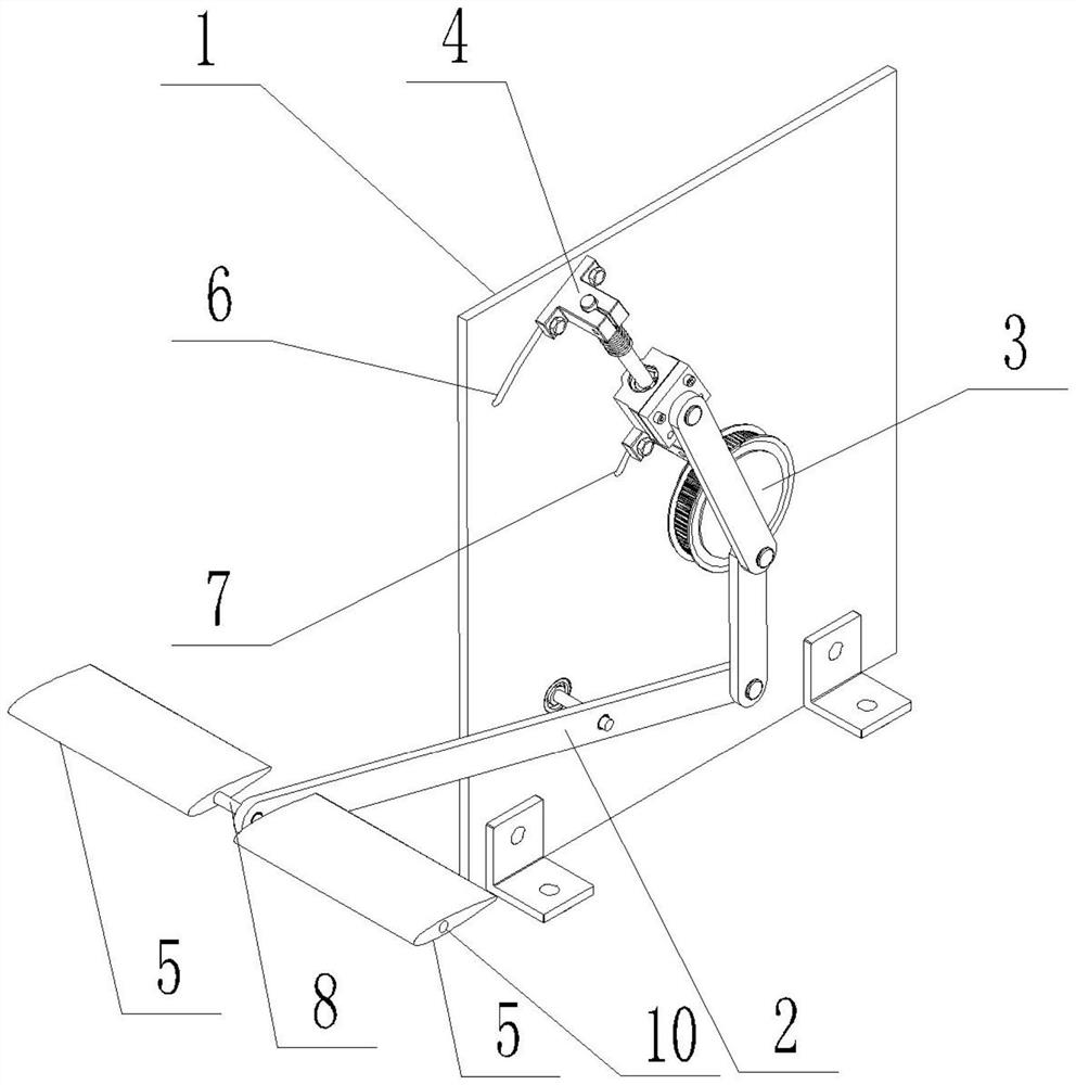
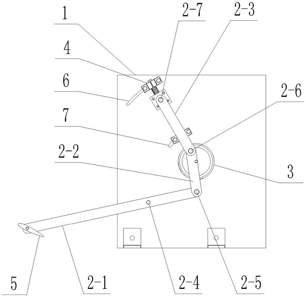
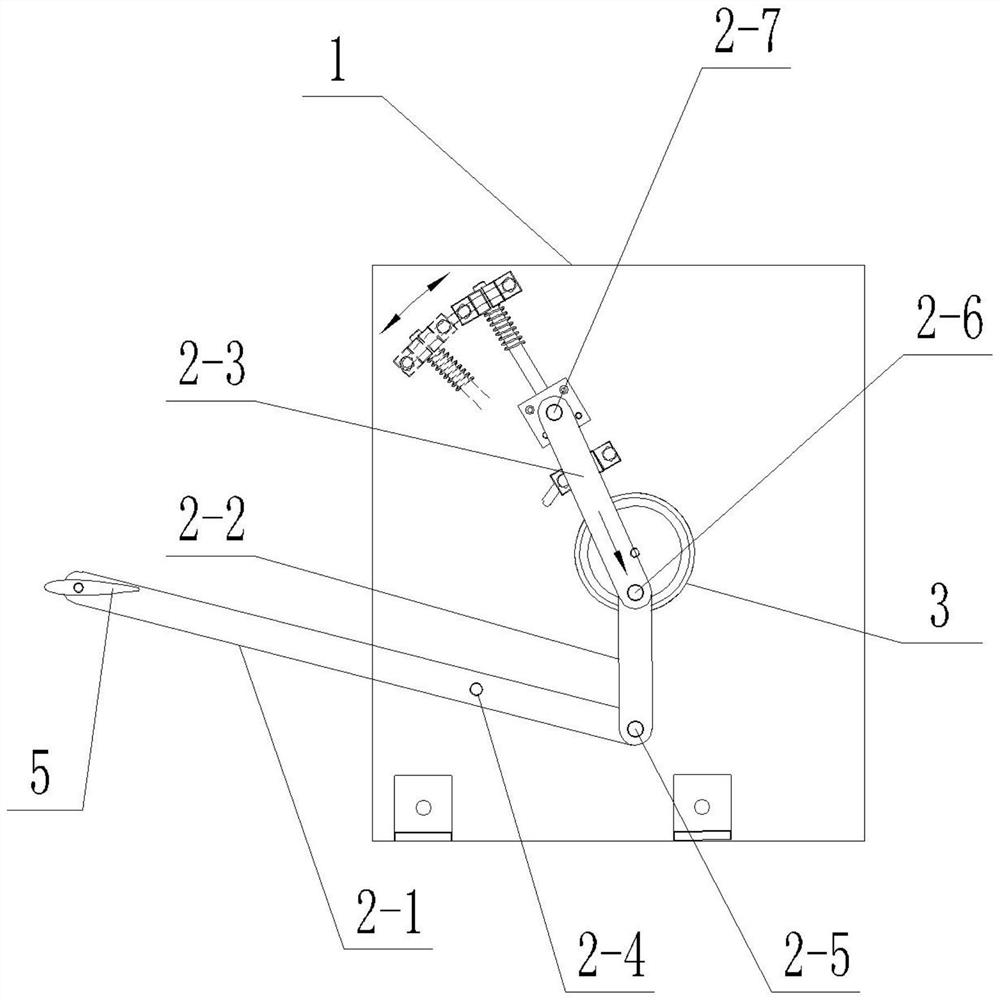
[0032] Specific implementation mode one: as figure 1 , figure 2 , image 3 , Figure 4 , Figure 5 , Figure 6 , Figure 7 , Figure 8 , Figure 9 and Figure 10 As shown, this specific embodiment adopts the following technical solutions. This embodiment includes a vertical plate 1, a transmission rod 2, a runner 3, an elastic slider body 4 and two hydrofoils 5, and the vertical plate 1 is vertically arranged. The transmission rod 2, the runner 3 and the elastic slider body 4 are all arranged on the same side of the vertical plate 1, the elastic slider body 4 is slidingly matched with the vertical plate 1, and the runner 3 is arranged under the elastic slider body 4;

[0033] The transmission rod 2 includes a long rod body 2-1, a middle rod body 2-2, a short rod body 2-3, a first shaft body 2-4, a second shaft body 2-5, a third shaft body 2-6 and a fourth shaft body The shaft body 2-7, one end of the long rod body 2-1 is hinged with two hydrofoils 5, the long rod bod...

specific Embodiment approach 2

[0039] Embodiment 2: This embodiment is a further limitation of Embodiment 1. The elastic slider body 4 includes an upper slide seat 4-1, a linear optical axis 4-2, a slide block 4-3, and a lower seat 4-4. , upper spring 4-5 and lower spring 4-6, described upper sliding seat 4-1 and lower sliding seat 4-4 are arranged on the side of vertical plate 1 successively from top to bottom, upper sliding seat 4-1 and lower sliding seat A linear optical axis 4-2 is arranged between 4-4, the slider 4-3 is set on the linear optical axis 4-2 and it reciprocates along the length direction of the linear optical axis 4-2, and the upper spring 4-5 is set on the On the linear optical axis 4-2 and it is between the upper slide seat 4-1 and the slider 4-3, the lower spring 4-6 is set on the linear optical axis 4-2 and it is located between the lower seat 4-4 and the slide block Between 4-3.

specific Embodiment approach 3

[0040] Specific embodiment three: this embodiment further defines the first arc-shaped slideway 6 matching the upper slide 4-1 on the side of the vertical plate 1 of the specific embodiment one or two, and the side surface of the vertical plate 1 is processed with Cooperate with the second curved slideway 7 of the sliding seat 4-4.

[0041] In this embodiment, the torque to overcome the dead point can be adjusted. The sliding fit relationship between the elastic slider body 4 and the vertical plate 1 is specifically that the upper sliding seat 4-1 is installed on the first arc of the vertical plate 1 through a plurality of first bolts. In the slideway 6, the sliding seat 4-4 is installed in the second arc-shaped slideway 7 of the vertical plate 1 through a plurality of second bolts.

[0042] In this embodiment, the position of the upper sliding seat 4-1 is changed by adjusting the fastening position of a plurality of first bolts in the first arc-shaped slideway 6, thereby real...


PUM


Abstract

The invention discloses a dead-point-free oscillating hydrofoil type tidal current energy power generation structural body. An existing hydrofoil type tidal current energy power generation device does not have a solution to solve the dead point problem. The dead-point-free oscillating hydrofoil type tidal current energy power generation structural body comprises a vertical plate, a transmission rod, a rotating wheel, an elastic sliding block body and two hydrofoil pieces, wherein the vertical plate is vertically arranged, the transmission rod, the rotating wheel and the elastic sliding block body are all arranged on the same side face of the vertical plate, the elastic sliding block body is in sliding fit with the vertical plate, and the rotating wheel is arranged below the elastic sliding block body; and two hydrofoil pieces are hinged to one end of a long rod body, the long rod body is hinged to the vertical plate through a first shaft body, the other end of the long rod body is hinged to one end of a middle rod body through a second shaft body, a third shaft body sequentially penetrates through the other end of the middle rod body and one end of a short rod body and then is arranged on the outer side face of a rotating wheel, and the other end of the short rod body is hinged to the elastic sliding block body through a fourth shaft body. The dead-point-free oscillating hydrofoil type tidal current energy power generation is used for tidal current power generation.

Description

Technical field: [0001] The invention specifically relates to an oscillating hydrofoil type tidal current energy generating structure without dead points. Background technique: [0002] Tidal current energy generation devices mainly adopt three types: horizontal axis type, vertical axis type and oscillating hydrofoil type. Among them, horizontal-axis and vertical-axis turbines are currently the main methods used in large-scale tidal current energy generation equipment. However, due to the complex structure of the water turbine, high installation and maintenance costs, and high requirements for water depth, its installation and application are greatly restricted. The oscillating hydrofoil power generation device uses the hydrofoil with a certain angle of attack to form a pressure difference between the front and the back, resulting in heave and pitch motions, and drives the generator to convert mechanical energy into electrical energy. Oscillating hydrofoil power generation...

Claims


Application Information

Patent Timeline
Patent Type & Authority Applications(China)
IPC IPC(8): F03B13/18F03B13/26F03B11/00
CPCF03B13/1815F03B13/26F03B11/00Y02E10/30Y02E10/20
Inventor 何广华赵志谦杨豪汪鹏莫惟杰王威朱一舟谢鸿飞
Owner HARBIN INST OF TECH AT WEIHAI
Learn More