Biplate lock mould structure injection moulding machine and its manufacturing method

An injection molding machine and mold clamping technology, which is applied in the field of manufacturing method and equipment structure of the mold clamping part of the injection molding machine, and achieves the effects of compact structure, simple production and simplified mold clamping procedure.

Inactive Publication Date: 2009-04-15
SUNNEX METAL PROD SHEN ZHEN
View PDF1 Cites 0 Cited by
  • Summary
  • Abstract
  • Description
  • Claims
  • Application Information

AI Technical Summary

Problems solved by technology

[0004] The technical problem to be solved by the present invention is to avoid the disadvantages of the above-mentioned prior art and propose a double-plate clamping structure injection molding machine with simple and firm clamping structure, simplified production and low cost and its manufacturing method

Method used


Image

  • Biplate lock mould structure injection moulding machine and its manufacturing method
  • Biplate lock mould structure injection moulding machine and its manufacturing method
  • Biplate lock mould structure injection moulding machine and its manufacturing method

Examples


Embodiment Construction

[0025] Below in conjunction with the best embodiment shown in the accompanying drawings, it will be further described in detail.

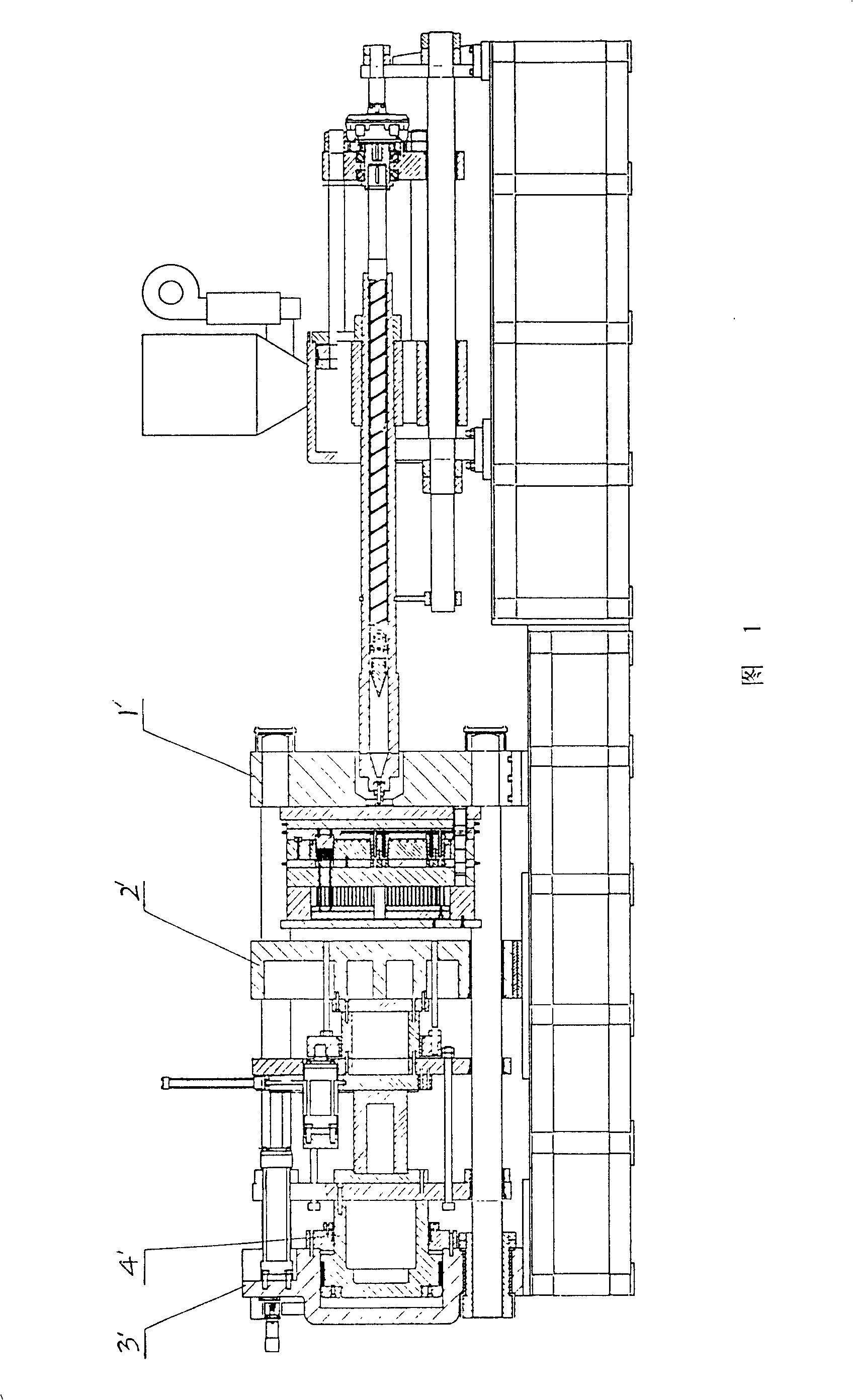
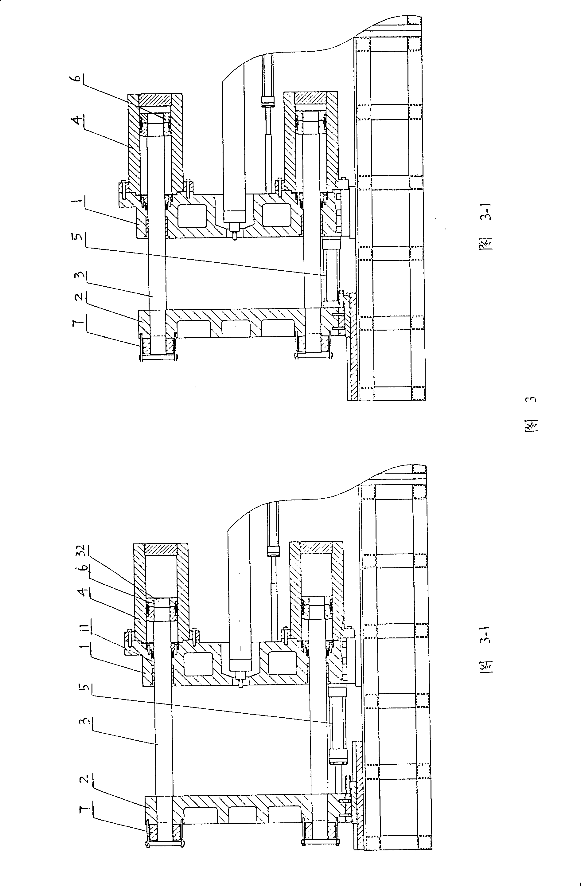
[0026] A method for manufacturing a double-plate clamping structure injection molding machine, as shown in Figure 3, comprising the following steps:

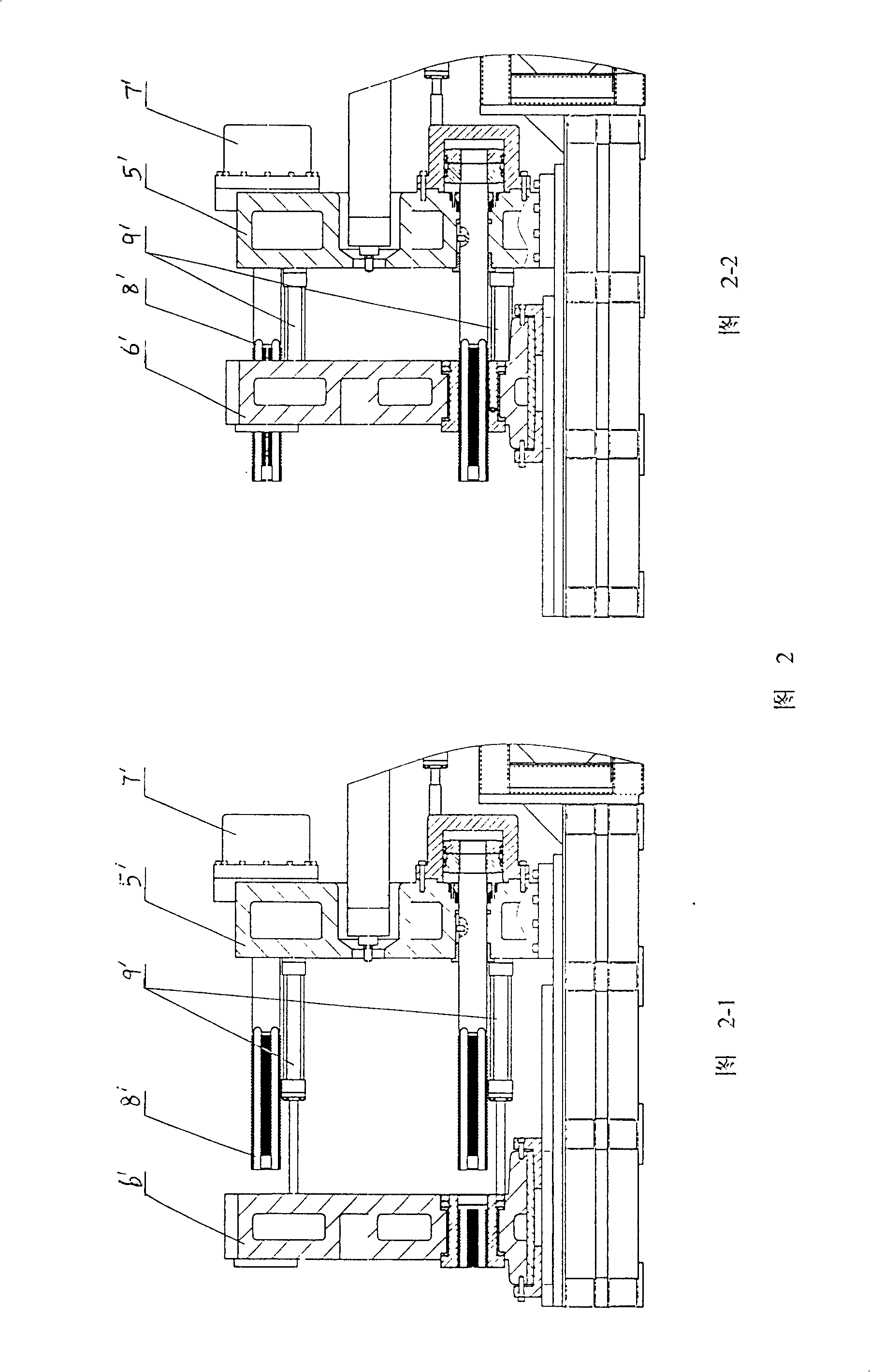
[0027] ①Arranging a fixed template 1, a movable template 2, four clamping rods 3 and a fast driving cylinder 5, and fixing the fast driving cylinder 5 between the fixed template 1 and the movable template 2;

[0028] ② Fix the front ends 31 of the four mold locking tie rods 3 to the four corners of the movable formwork 2 respectively by means of fasteners, and the tail ends 32 of the four mold locking tie rods 3 pass through the four corners of the fixed formwork 1 corner through hole 11;

[0029] ③ After the tail end 32 of the mold clamping tie rod 3 passes through the through hole 11, a piston 6 is sleeved and fixed on the tail end 32 so that the mold clamping tie rod 3 and the piston 6 are fixed ...


PUM


Abstract

An injection moulding machine with dual-plate mould-locking structure features that its mould-locking pull rod is permanently connected to slide template via locking nut and the other end of said pull rod is integrated with the piston in mould-locking cylinder, so whole assembly can only move left and right. The diameter and length of piston tail are increased, so it can run outside the cylinder to decrease the amount of oil sucked and discharged by mould-locking cylinder. Its advantages are high strength and mould-locking speed, low cost and low energy consumption.

Description

technical field [0001] The invention relates to an injection molding machine, in particular to a manufacturing method and equipment structure of the clamping part of the injection molding machine. Background technique [0002] The traditional full hydraulic clamping injection molding machine is shown in Figure 1, the left side is the clamping combination part, and the right side is the injection combination part. The clamping combination part is composed of three templates, among which template 1' is a fixed plate for installing the front mold of the injection mold, template 2' is a movable template for installing the rear mold, and template 3' is also a fixed plate for To assist template 2' movement. The template 2' and the template 3' are connected by a large mold clamping oil cylinder 4', which is used to counteract the huge pressure of injection, and most of the cost of the injection molding machine is used for the mold clamping combination. [0003] In order to reduce...

Claims


Application Information

Patent Timeline
Patent Type & Authority Patents(China)
IPC IPC(8): B29C45/67
Inventor 余达澄
Owner SUNNEX METAL PROD SHEN ZHEN
Why Eureka
Try Eureka